


ELECTRICAL SYSTEM
The electrical system on every Great Dane trailer
meets or exceeds all federal and state requirements in
effect at the time of manufacture. Wherever required
by law, lamps and reflectors are marked by the
m
anufacturer to indicate the appropriate specification
with which each complies.
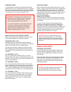
For optimum performance and long life from the trailer’s
lamps and wiring, follow this inspection procedure.
Clean all reflective tape or devices and lamps. See that
all lamps burn properly. Replace all burned-out lamps
and broken or missing reflective devices. Factory-
approved replacement parts should be used, and
replacement bulbs of equal candlepower should be
used for safety.
NOTE: Electrical circuits may be protected by circuit
breakers located inside the front nose box.
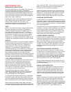
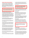
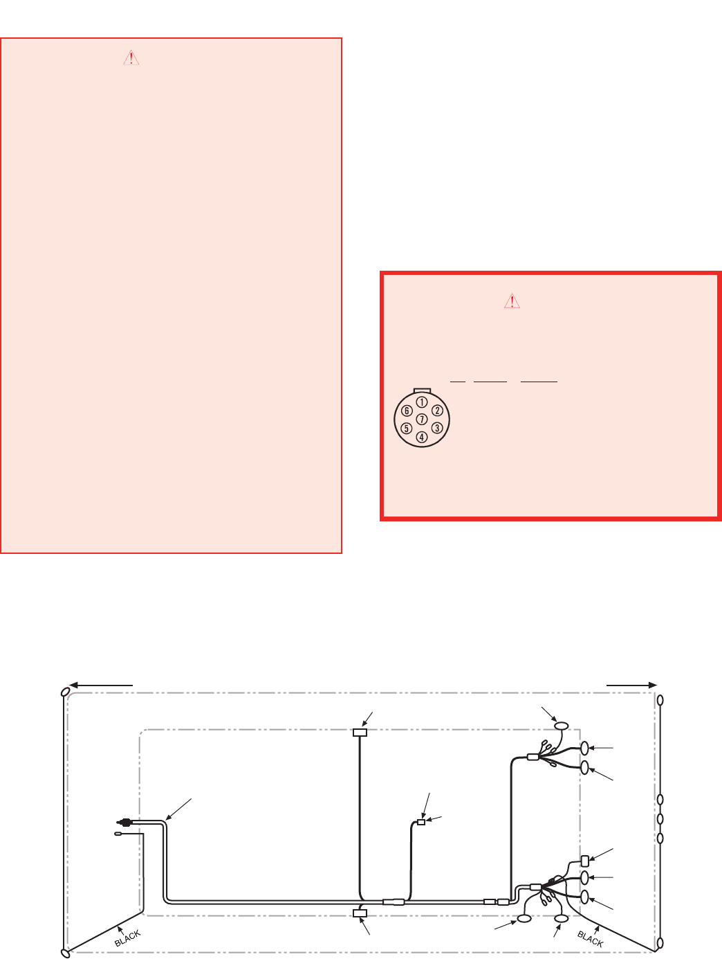
TRAILER IS EQUIPPEDWITH ANTILOCK BRAKESYSTEM (ABS).NO.7
(BLUE) CIRCUIT IS RESERVEDFOR CONTINUOUS POWER SUPPLYTO
ABS.FOR MOSTEFFECTIVE ABS OPERATION,TOWINGVEHICLE MUST
SUPPLY MINIMUM OF 10 AMPS AT 12.5 VOLTS TO NO. 4 (RED) &
NO. 7 (BLUE) CIRCUITS.
PIN
COLOR CIRCUIT
1 WHITE GROUNDRETURNTOTOWINGVEHICLE
2 BLACK CLEARANCE,SIDE MARKER& ID LAMPS
3 YELLOW LEFTTURN SIGNAL & HAZARD LAMPS
4 RED STOP LAMPS & ABS POWER
5 GREEN RIGHTTURN SIGNAL &HAZARD LAMPS
6 BROWN TAIL,LICENSE,CLEARANCE &
SIDEMARKER LAMPS
7 BLUE ABS CONTINUOUS SHARED POWER
FAILURETO HEEDTHISWARNING CANRESULT IN PROPERTY
DAMAGE,SERIOUS INJURYOR DEATH.
WARNING
J560
SOCKET
6
CAUTION
CONNECTOR WIRING CHANGE
NOTICE TO ALL
TRACTOR-TRAILER OWNERS AND USERS
Federal Motor Vehicle Safety Standard No. 121,
Air Brake Systems, was amended by the National
Highway Traffic Safety Administration of DOT to
require that truck tractors manufactured on or after
March 1, 1997, provide constant power for a trail-
er’s antilock brake system (ABS). Some manufac-
turers provided this feature before the effective
date. These tractors using a single 7-way
electrical connector will have constant power
for ABS on the center pin when the key switch
is on. Tractor-trailer owners and users who
presently use the center pin for auxiliary power to
equipment other than trailer ABS (for example,
dome lights, backing lights, bottom dumps, sliding
undercarriages, air ride dump valves, etc.) will be
affected by this change. In certain uses of this
constantly powered center pin connector,
unexpected or unintended activation of this
equipment may be hazardous or result in
personal injury. Before connecting your tailer to a
tractor, MAKE SURE that the constantly powered
center pin WILL NOT UNINTENTIONALLY TURN
ON TRAILER EQUIPMENT. If you have any
questions about your present wiring, or how to
rewire your vehicles, you should contact the tractor
manufacturer, auxiliary equipment manufacturer,
and/or Great Dane Trailers Customer Service
Department.
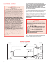
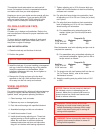
WIRING DIAGRAM
GREEN
BROWN
WHITE
YELLOW
BROWN
WHITE
WHITE
WHITE-GREEN
BROWN
BROWN
GREEN
BROWN
WHITE
RED
BROWN
WHITE
BROWN
RED
BROWN
WHITE
YELLOW
BROWN
WHITE
7 COND MAIN HARNESS
4 CONDABS HARNESS
— TOP VIEW OF TRAILER —FRONT REAR
BLUE
WHITE
WHITE-GREEN
RED