


20
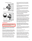
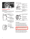
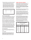
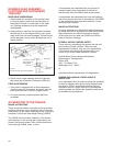
5. Measure the distance, on each side, from the center
of the end of the front axle to the center of the end
of the rear axle (measurements C and D of the
tandem-axles illustration). These measurements
m
ust be within 1/16" of each other. (Illustrated is a
gauge that simplifies this measurement.) It can be
made of drill rod or pipe fittings. The materials and
details are less important than that the resulting
gauge be rigid and true. (The pointer arms of the
gauge should be parallel and in the same plane.)
CORRECTING MISALIGNMENT
If any of the related measurements are not within stated
dimensions, inspect the trailer suspension thoroughly
for loose, worn, or broken connecting and supporting
parts. Replace worn or broken parts. Then adjust the
suspension to bring the axle or axles into alignment.
When there is a slight amount of irreducible misalign-
ment in one axle assembly of a tandem-axles trailer,
the other can sometimes be moved a corresponding
amount in the opposite direction to reduce the tendency
of the trailer to “dogtrack”, but it should not be moved
more than 1/16" from its optimum alignment position.
This method of correcting misalignment is not recom-
mended as a permanent and sound solution – there is
no substitute for correctly installed and aligned axles.
The limits of 1/8" appear very small compared with the
overall dimensions of the trailer, but they are recog-
nized as the maximum permissible limits of misalign-
ment. Also, the relatively small size of these limits
makes it important that the measurements be accurate.
TOE-IN AND TOE-OUT
Toe-in and toe-out can be checked accurately with
front axle aligning equipment designed for automotive
service.
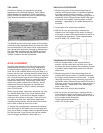
AXLE CAMBER
Axle camber should be measured accurately on an
alignment machine made for the purpose. It is often
advisable to consult a qualified specialist with the
equipment both to measure and to correct errors of
camber. NOTE: Most trailer axles have no camber.
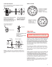
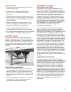
UPPER COUPLER & KINGPIN
I
nspect the kingpin and the upper coupler on the trailer
at regular intervals to be sure that they have not
suffered damage or undue wear. Although the kingpin
is made of hardened forged steel, it is still subject to
wear and can be chipped or broken with abuse.
A
lways check the bottom locking flange of the kingpin
to determine its condition. The upper coupler fasteners
should be inspected to see that they are in place and
properly tightened.
Before coupling the trailer to its tractor be certain that
the tractor fifth wheel is properly lubricated and the fifth
wheel jaws are open to receive the kingpin.
If the bottom rail attachment fasteners of a van upper
coupler are damaged they should be replaced with
fasteners of the same design and strength. Loose or
missing fasteners must be replaced. Great Dane should
be contacted for replacement information. If this infor-
mation is not available, Grade 5 (minimum) bolts and
Grade B (minimum) locking type nuts may be used but
must be torqued properly.
Be careful in selecting the proper bolt grip length so
that threads are not at the interface of the coupler/rail
joint. It is recommended that, if possible, the next
larger diameter fastener should be used to provide a
good tight fit. If this is not practical, then replace the
fastener with the same size as removed. Drill a
companion hole of the same diameter with proper
spacing between the holes and add an additional
fastener. This method assures adequate fasteners to
contain the upper coupler loads.
BOLT TORQUE REQUIREMENTS
CLEAN DRY THREADS
LB-FT
BOLT SIZE GRADE 5 GRADE 8
3/8" UNC 30 45
3/8" UNF 35 50
1/2" UNC 75 110
1/2" UNF 90 120
5/8" UNC 150 220
5/8" UNF 180 240
1" UNC 580 900
1" UNF 640 1000