


16 GMR 20/40 Owner’s Manual
GMR 20/40 OPERATION > THE RADAR ADJUSTMENT MENU
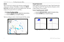
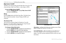
Center Offset—has three settings: Center, Look Ahead, and Auto
Shift. Center places your current location in the center of the display.
Look Ahead shifts your current location toward the bottom of the
display, allowing you to view an area farther ahead. Auto Shift adjusts
your location on the display according to the current speed.
Rings—is used to turn the radar Range Rings On or Off.
Background—
is used to select a background color for the Radar
page. The options are Black, Blue, and White.
Heading Line—is used to turn the Heading Line On or Off.
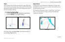
Bearing Reference—has two settings, Absolute and Relative.
Relative calculates the bearing relative to own vessel heading.
Absolute calculates the bearing referring to North.
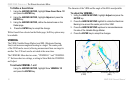
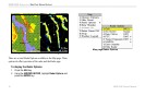
Navigation Features—there are three selectable Navigation
Features: Waypoints, Bearing Line, and Course Line. When selected,
that feature is displayed on the Radar page.
• Waypoints
—displays user waypoints on the Radar page.
•
Bearing Line—when selected displays a Bearing Line on the
Radar page. The Bearing Line is displayed as a line from your
current position to the active destination waypoint, similar to
a traditional lollipop.
•
Course Line—when selected displays a Course Line from
your starting point to the active destination waypoint, similar
to navigation on a map.
The MARPA Tab
See MARPA Setup on page 12.
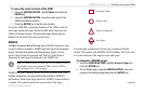
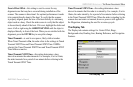
The Advanced Tab
AFC Mode—has two settings, Auto, and Manual. In Auto Mode the
scanner frequency is automatically adjusted for optimal performance
and is recommended.
The Advanced Tab