


7
If a problem is found, try altering the location of the
unit or wiring. Often moving the antenna a few feet away
from the source of interference will solve the problem.
When a suitable configuration is found, a permanent
installation should be made.
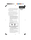
The GBR 21 may be mounted on any flat surface.
Select the mounting location according to your
preferences— either an out-of-the-way location (such as
under the dash) or at an accessible location where the
LED status light will be visible. Keep in mind that from
this mounting location cables will be routed to the
antenna and to the GPS unit.
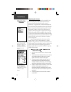
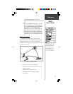
1. Drill the mounting holes (4) for the GBR 21
according to the mounting hardware that will be
used. Mounting hardware is not included with the
GBR 21. You should select the mounting hardware
suitable for your installation. Stainless steel (#4 or
#6 diameter) hardware is recommended. A
mounting template is provided inside the back cover
of this manual.
2. Mount the GBR 21 at this location using the
selected hardware.
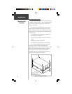
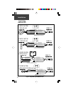
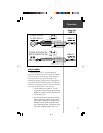
3. Connect the power/data cable to the GBR 21,
observing the proper polarity as indicated by the
notch in the connector.
Figure 2: GBR 21 Cable Connections
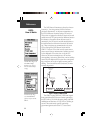
4. Connect the RED wire from the power/data cable to
an accessory switch on the dash. If an accessory
switch is not available, a standard SPST switch may
be used (not included).
5. Connect the other end of the accessory switch to
the ship’s positive 10-18 Volt DC power source.
6. Connect the BLACK wire from the power/data cable
to vessel ground (or the negative terminal of the
ship’s 10-18 Volt DC power source).
Installation
Mounting the
Receiver
Alignment Notch
Power/Data ConnectorBNC Connector