


11
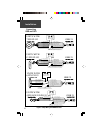
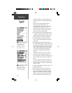
GBR 21
10-18 VDC
(7) YELLOW
:
GROUND
(6) GREEN: BAUD SELECT OUT
(5) WHITE: BAUD SELECT IN
JUMPER THESE TOGETHER FOR 9600 BAUD.
LEAVE THESE UNCONNECTED FOR 4800 BAUD.
UNITS WITH
18 PIN PLUG
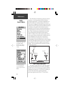
GBR 21
10-18 VDC
JUMPER THESE TOGETHER FOR 9600 BAUD.
LEAVE THESE UNCONNECTED FOR 4800 BAUD.
UNITS WITH 4 PIN,
RECTANGLE PLUG
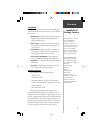
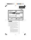
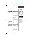
(1) RED: 10-18 VDC
(2) BLACK: GROUND
(4) BROWN: DATA IN
(15) RED: POWER INPUT
(18) BLACK: GROUND
(3) BLUE: DATA OUT
(17) BLUE: DATA OUT
(16) BROWN: DATA IN
(11) YELLOW: ALARM
(1-10,12-14) NOT USED
(7) YELLOW
(6) GREEN: BAUD SELECT OUT
(5) WHITE: BAUD SELECT IN
(1) RED: 10-18 VDC
(2) BLACK: GROUND
(4) BROWN: DATA IN
(3) BLUE: DATA OUT
(2) GREEN: DATA IN
(3) WHITE: DATA OUT
(4) BLACK: GROUND
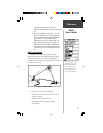
1
23
4
1
2
6
3
7
11
12
15
16
18
(Not used)
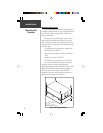
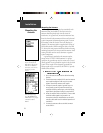
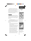
Using the GBR 21
When using the GBR 21, all tuning/operation
functions are controlled by the GPS unit. Your GARMIN
GPS unit provides a Beacon Receiver Setup Page and, in
some cases, Beacon Log Page for this purpose. The
operating instructions provided below are generalized to
cover several different GARMIN models. For additional
information on operating your GPS unit with the GBR 21,
refer to the owner’s manual for your GPS unit.
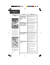
1. Turn the power on to the GBR 21. The LED
status light will flash indicating power has been
applied, but no beacon signal is being received.
2. Turn the GPS unit on.
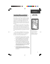
3. From the Interface Setup Page, select an RTCM
input. If a baud rate selection is also provided,
specify 4800 or 9600 baud, as appropriate. On
GARMIN GPS units, RTCM input/NMEA 0183
output should be selected. The baud rate will be
set to 4800. If additional devices, such as an
Operation
Using the
GBR 21
Figure 3 (cont.): Sample Wiring to GARMIN GPS Units