GPS 18 Technical Specifications (190-00307-00) Rev. D
Page 13
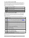
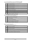
4.1.2 Sensor Initialization Information (PGRMI)
The $PGRMI sentence provides information used to initialize the GPS sensor’s set position and time used
for satellite acquisition. Receipt of this sentence by the GPS sensor causes the software to restart the
satellite acquisition process. If there are no errors in the sentence, it will be echoed upon receipt. If an error
is detected, the echoed PGRMI sentence will contain the current default values. Current PGRMI defaults
(with the exception of the Receiver Command, which is a command rather than a mode) can also be
obtained by sending $PGRMIE to the GPS sensor.
$PGRMI,<1>,<2>,<3>,<4>,<5>,<6>,<7>*hh<CR><LF>
<1> Latitude, ddmm.mmm format for GPS 18 PC/LVC; ddmm.mmmmm format for GPS 18-
5Hz (leading zeros must be transmitted)
<2> Latitude hemisphere, N or S
<3> Longitude, ddmm.mmm format for GPS 18 PC/LVC; ddmm.mmmmm format for GPS 18-
5Hz (leading zeros must be transmitted)
<4> Longitude hemisphere, E or W
<5> Current UTC date, ddmmyy format
<6> Current UTC time, hhmmss format for GPS 18 PC/LVC; hhmmss.s format for GPS 18-5Hz
<7> Receiver Command, A = Auto Locate, R = Unit Reset
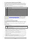
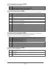
4.1.3 Sensor Configuration Information (PGRMC)
The $PGRMC sentence provides information used to configure the GPS sensor’s operation. Configuration
parameters are stored in non-volatile memory and retained between power cycles. The GPS sensor will
echo this sentence upon its receipt if no errors are detected. If an error is detected, the echoed PGRMC
sentence will contain the current default values. Current default values can also be obtained by sending
$PGRMCE to the GPS sensor.
$PGRMC,<1>,<2>,<3>,<4>,<5>,<6>,<7>,<8>,<9>,<10>,<11>,<12>,<13>,<14>*hh<CR><LF>
<1> Fix mode, A = automatic, 2 = 2D exclusively (host system must supply altitude),
3 = 3D exclusively
<2> Altitude above/below mean sea level, -1500.0 to 18000.0 meters
<3> Earth datum index. If the user datum index (96) is specified, fields <4> through <8> must
contain valid values. Otherwise, fields <4> through <8> must be null. Refer to Appendix A:
Earth Datum List for a list of earth datum and the corresponding earth datum index.
<4> User earth datum semi-major axis, 6360000.000 to 6380000.000 meters (.001 meters
resolution)
<5>
User earth datum inverse flattening factor, 285.0 to 310.0 (10
-9
resolution)
<6> User earth datum delta x earth centered coordinate, -5000.0 to 5000.0 meters (1 meter
resolution)
<7> User earth datum delta y earth centered coordinate, -5000.0 to 5000.0 meters (1 meter
resolution)
<8> User earth datum delta z earth centered coordinate, -5000.0 to 5000.0 meters (1 meter
resolution)
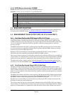
<9> Differential mode, A = automatic (output DGPS data when available, non-DGPS otherwise), D
= differential exclusively (output only differential fixes)
<10> NMEA 0183 Baud rate, 1 = 1200, 2 = 2400, 3 = 4800, 4 = 9600, 5 = 19200, 6 = 300, 7 = 600,
8 = 38400 (for GPS 18-5Hz only)
<11> Velocity filter, 0 = No filter, 1 = Automatic filter, 2–255 = Filter time constant
(for example, 10 = 10 second filter)
<12> Measurement Pulse Output, 1 = Disabled, 2 = Enabled
<13> Measurement Pulse Output pulse length, (n+1)*20 ms
For 18 LVC/PC n = 0 through 48 (max. 980 ms)
For GPS 18-5Hz n = 0 through 8 (max. 180 ms)
Example: n = 4 corresponds to a 100 ms wide pulse
<14> Dead reckoning valid time 1 to 30 sec. for the GPS 18 PC/LVC
or 0.2 to 30.0 sec. for the GPS 18-5Hz
All configuration changes take effect after receipt of a valid value except baud rate and Measurement Pulse
Output mode. Baud rate and Measurement Pulse Output mode changes take effect on the next power cycle
or an external reset event.


