


Av. Kit Install. Manual
190-00004-00 Rev. G
Page 9
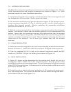
3.2 ANTENNA INSTALLATION
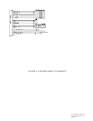
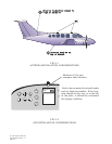
The Blade Antenna outline and footprint dimensions are shown in Figure 3-1. The Low
Profile Antenna outline and footprint dimensions are shown in Figure 3-1A. Both
antennas require the same Installation procedure.
A. Using the backing plate as a template, mark the location of the mounting holes and
the through hole for coax cable. Drill or punch the holes.
B. The antenna installation must provide adequate support for the antenna consid-
ering a maximum drag load of 14 lbs (at subsonic speed). Install a doubler plate to
reinforce thin skinned aircraft. Observe guidelines for acceptable installation
practices as outlined in AC 43.13-2A.
C. Seal the antenna and gasket to the fuselage using a good quality electrical grade
sealant. Use caution to insure that the antenna connector is not contaminated with
sealant. Insure that the mounting screws are fully tightened and that the antenna
base is well seated against the gasket. CAUTION: Do not use construction grade RTV
sealant or sealants containing acetic acid. These sealants may damage the electrical
connections to the antenna. Use of these type sealants may void the antenna
warranty.
3.3 CABLE INSTALLATION
A. Route the coax cable supplied to the rack location keeping in mind the recommen-
dations of Section 2. Secure the cable in accordance with good aviation practice.
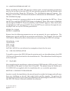
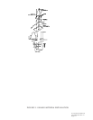
B. Trim the supplied RG-59/U cable to the desired length and install the BNC
connector (330-00017-00) per the cabling instructions on Figure 3-2.
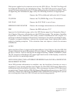
3.4 RACK INSTALLATION
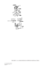
A. Figure 3-3 shows outline dimensions for the aviation rack. Install the rack in a
rectangular 6.320" x 2.000" hole in the instrument panel. Exercise caution when
installing the rack into the instrument panel. The rack is designed to facilitate removal
of the GPS 100 for portable use. Deformation of the rack may make it difficult to install
and remove the GPS 100.
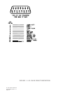
B. Install the rack in the aircraft panel using four #6-32 countersunk screws and
four self-locking nuts. The screws are inserted from the inside through the holes
in the sides of the rack (see Figure 3-4).