


Av. Kit Install. Manual
190-00004-00 Rev. G
Page 6
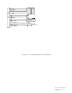
1.2.3 Interfaces
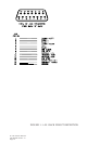
The aviation rack contains an electronic module which provides interfaces to various
general aviation instruments. Figure 1-1 defines the function of each pin on the 15
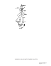
pin DSUB connector located at the back of the rack. Figure 1-2 depicts the
interconnects between the rack and other instruments. The following interfaces are
provided.
CDI: Capable of driving up to three 1000 ohm parallel
(Pins 1 and 4) loads, +150 millivolts full scale deflection with a
maximum output of +300 millivolts.
To/From: Capable of driving up to three 200 ohm parallel
(Pins 2 and 5) loads, +82 millivolts full scale deflection.
Nav Flag: Capable of driving up to three 1000 ohm parallel
(Pins 3 and 6) loads, 375 millivolts for flag out-of-view, and
+40 millivolts for flag in-view.
OBI data: Output providing bearing to waypoint data for a
(Pins 7, 8, and 12) Bendix/King RMI (KI 229 or equivalent).
Message annunciators: Output capable of driving negative or positive logic
(Pins 9 and 11): annunciators.
Message audio: Output capable of producing 10 milliwatts into 500
(Pin 10) ohms at a frequency of 2 KHz.
RS232 data: Output capable of driving ARGUS3000/5000/7000
(Pin 13) and STORMSCOPE SERIES II with NAVAID moving
map displays and Shadin fuel management system.
Conforms to the EIA specification RS-232C.
SECTION 2 INSTALLATION CONSIDERATIONS
Careful planning and consideration of the suggestions in this section are required to
achieve the desired performance and reliability from the GPS 100.
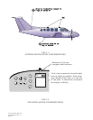
2.1 ANTENNA CONSIDERATIONS
2.1.1 SATELLITE VISIBILITY
The GPS 100 Blade or Low Profile Antenna must be mounted on top of the aircraft in
the upright position. For best performance select a location with an unobstructed
view of the sky above the aircraft when in level flight. Figure 2-1 illustrates a typical
blade antenna installation. Recommended installation locations for the Low Profile
Antenna are the same.