


Av. Kit Install. Manual
190-00004-00 Rev. G
Page 7
2.1.2 NOISE SOURCES
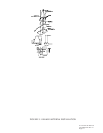
The antenna should be located at least 3 ft from transmitting antennas such as VHF
Comm, HF transmitter, DME, Transponder, and Radar. Cabling for the GPS 100
should not be routed near components or cabling which are sources of electrical noise.
2.1.3 ELECTRICAL BONDING
No special precautions need to be taken to provide a bonding path between the
antenna and the aircraft structure.
2.1.4 ANTENNA LIMITATIONS
The GPS 100 Blade and Low Profile Antennas are recommended for installations
where the airspeed of the aircraft will be subsonic. For aerodynamic considerations,
the Low Profile Antenna is recommended for operation above 200 kts.
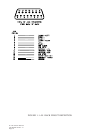
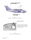
2.2 RACK CONSIDERATIONS
2.2.1 ACCESSIBILITY
Plan a location which gives the pilot complete and comfortable access to the entire
keypad and which is plainly visible from the pilots perspective. Check that there is
adequate depth for the rack in the instrument panel. A location away from heating
vents or other sources of heat generation is optimal. Figure 2-2 illustrates a typical
aviation rack installation.
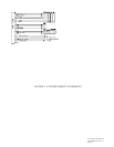
2.3 CABLING AND WIRING
Use only the antenna cable supplied in the installation kit. Other cabling may lead
to degraded performance. Check that there is ample space for the cabling and mating
connectors. Avoid sharp bends in cabling and routing near aircraft control cables.
2.4 ANNUNCIATORS
If the installation includes any electrical interface with other flight instruments, an
annunciator may be required. Refer to current FAA directives.