


A–3
A.3 Wiring
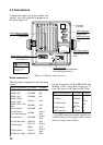
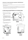
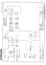
1. Connect wire assembly disconnected in step 2 in the previous section between J12 on the
BUFFER Board and DJ-1 on the rear chassis. (Because the wire assembly is long, be sure it
does not touch the FIL Board or CRT. Locate it near the BUFFER Board.)
2. On the BUFFER Board, connect the appropriate wire assembly (supplied) as follows;
1720 Series (wire assy. 1): 11P connector to J22 and 3P connector to J11
1830/FR-7000D Series (wire assy. 2): 9P connector to J22 and 3P connector to J11
1721 Series (wire assy. 3): 14P connector to J22 and 3P connector to J11
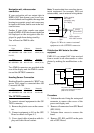
3. Route the wire assembly connected at step 2 to the SPU Board through the path previously
used to pass wire assembly between DJ-1 and the SPU Board. Connect the wire assembly to
the SPU Board as follows;
1720 Series: 3P connector to J57 and 11P connector to J52
1830/FR-7000D Series: 3P connector to J57 and 9P connector to J52
1721 Series: 3P connector to J57 and 14P connector to J52
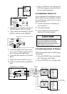
4. Make a hole in "OPTION" on the rear of the remote display and connect the signal cable
(supplied with FMD-811) there. Connect the other end of the signal cable to J21 on the
BUFFER Board. Seal the hole with sealing putty.
5. Confirm wiring. Attach cover of main radar.
A.4 Operation Checks
1. Connect antenna and power cables. Turn on the main radar.
2. Transmit the main radar. Confirm that the picture is as before the installation.
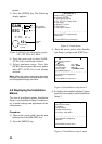
3. Turn on the remote display and set it to transmit condition. Confirm that the same picture
appears on both the main radar and the remote display.
4. Confirm that the picture on the main radar does not change when the remote display is oper-
ated.