


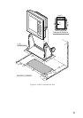

A–1
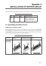
Appendix A
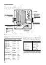
INSTALLATION OF BUFFER CIRCUIT
The optional buffer circuit enables connection of the FMD-811 to the radars listed in Table 1.
Table 1 Buffer circuit and applicable radars
emaN.oNedoCepyTsradaRelbacilppA
reffuB
BWP
tiK
070-174-800731-30PO0671/0571/0371/0271LEDOM
0491/0391/0381LEDOM
D0017/D0407/D0107-RF
1671/1571/1371/1271LEDOM
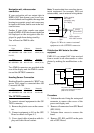
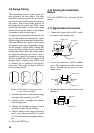
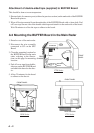
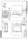
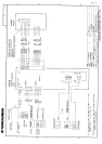
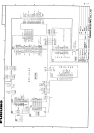
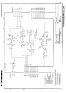
A.1 Assembling the Buffer Circuit
Soldering of connector posts
Solder appropriate I/O signal connector post (supplied) to both J12 and J22 on the BUFFER
Board (03P9199). (Solder connector posts with their #1 pin mated with corresponding #1 pin
on the BUFFER Board.) Three types of connector posts are supplied. Select proper connector
posts according to main radar by referring to the table below.
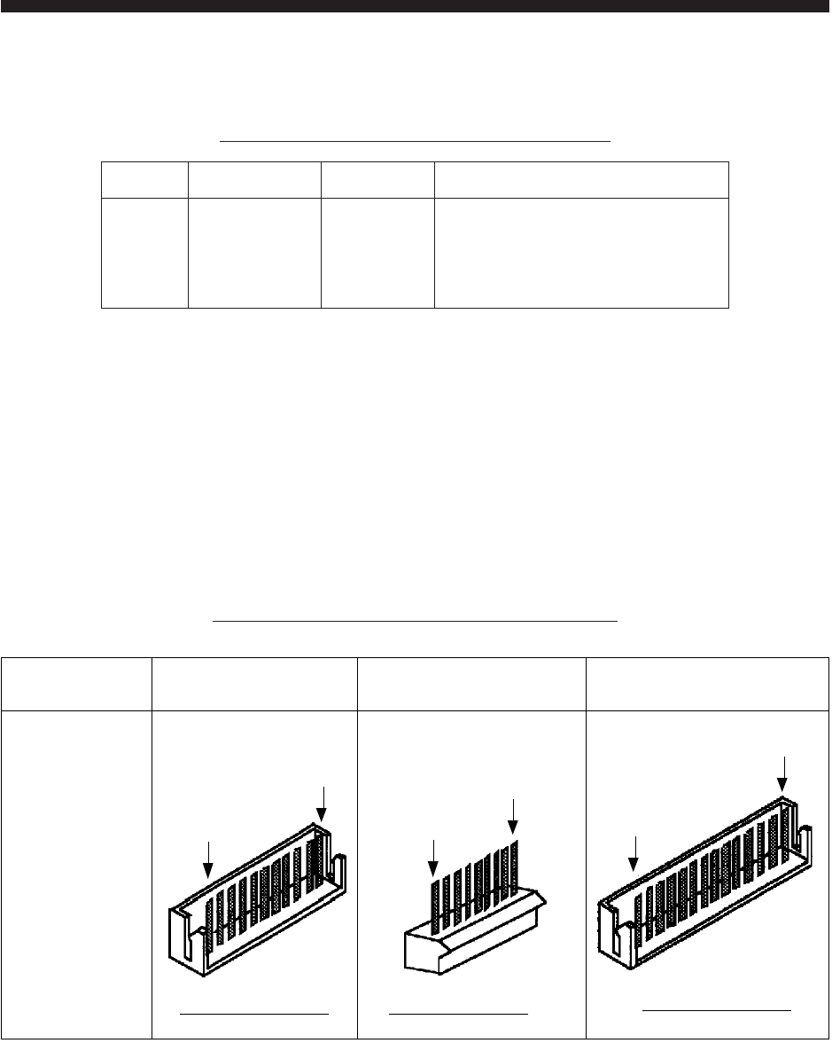
Table 2 Main radar and connector post to use
Main radar MODEL 1720,1730,
1750, 1760
MODEL 1830, 1930, 1940
FR-7010D/7040D/7100D
MODEL 1721, 1731, 1751,
1761
Connector
post to solder
to J21 and J22
#1 pin
#11 pin
#1 pin
#9 pin
#1 pin
#14 pin
11P connector post 9P connector post
14P connector post