


31
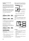
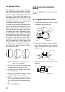
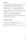
5. Add jumper wire between J55 pin #3
(RXD-H) and J61 PIN #1 (TXD-H).
6. Add a jumper wire between J55 pin #4
(RXD-C) and J61 pin #5 (SHIELD).
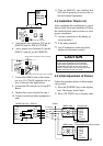
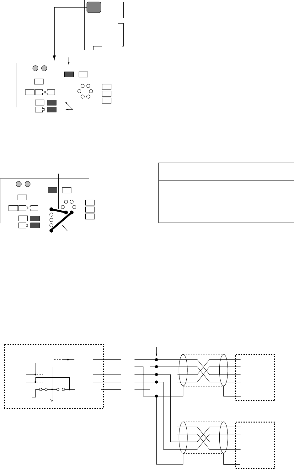
7. Connect the NMEA cable to the connec-
tor assy (03-1796/5P, supplied with ra-
dar) as shown in the figure below.
8. Connect the 5P connector to J51 on SPU
Board.
9. Replace the covers removed in step 1.
10. Connect navaid and other equipment to
radar.
11. Turn on FMD-811 and confirm that
NAV data in properly received at the ra-
dar and external equipment.
4.4 Installation Check List
After completing the installation it is a good
idea to check for proper installation. Follow
the checklist below and tick boxes to show
proper completion.
❒ Are the connections to the battery of
correct polarity?
❒ Is the unit grounded?
❒ Are all connectors at the rear of the
display unit fastened securely?
CAUTION
If it is necessary to open the display unit, be sure
the rear cover is fitted to the front chassis
properly when closing the rear cover. When
reassembling, first turn off the unit and then
press the center of the rear cover to plug in the
multipin connector on the rear cover.
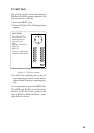
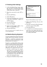
4.5 Initial Adjustment of Picture
Follow the procedure below to obtain proper
radar picture.
1) Press the [POWER] key on the display
unit. The display should light.
2) Press [TX ST-BY] key to display radar
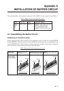
SPU-9180
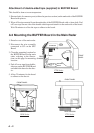
Parts side
CR14
Q15
R91
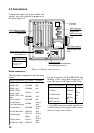
Remove R91 and R92.
R92
R93
R94
R95
Q16
R90
R91
Remove JP3.
JP3 JP4
CR14
Q15
R91
R69
34
51
C27
R70
Add the jumper wire between J61#1 and J55#3.
R92
R93
R94
R95
Q16
R90
R91
Add the jumper wire between J61#5 and J55#4.
JP3 JP4
J55
J61
MODEL 821/841 • FMD-811
NMEA cable
Solder
Echosounder
J55
TX-H
TX-C
RD-H
RD-C
N.C
SHIELD
J61
TX-H
TX-C
RD-H
RD-C
SHIELD
TX-H
TX-C
RD-H
RD-C
N.C
SHIELD
TX-H
TX-C
RD-H
RD-C
N.C
SHIELD
JP4 JP3
03-1796 (5P)
BRN
RED
ORG
YEL
GRN
NMEA cable
Other Equipment
(Telesounder data not be mixed.)