


9
WIRING
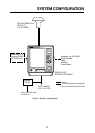
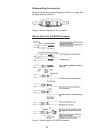
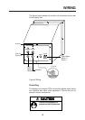
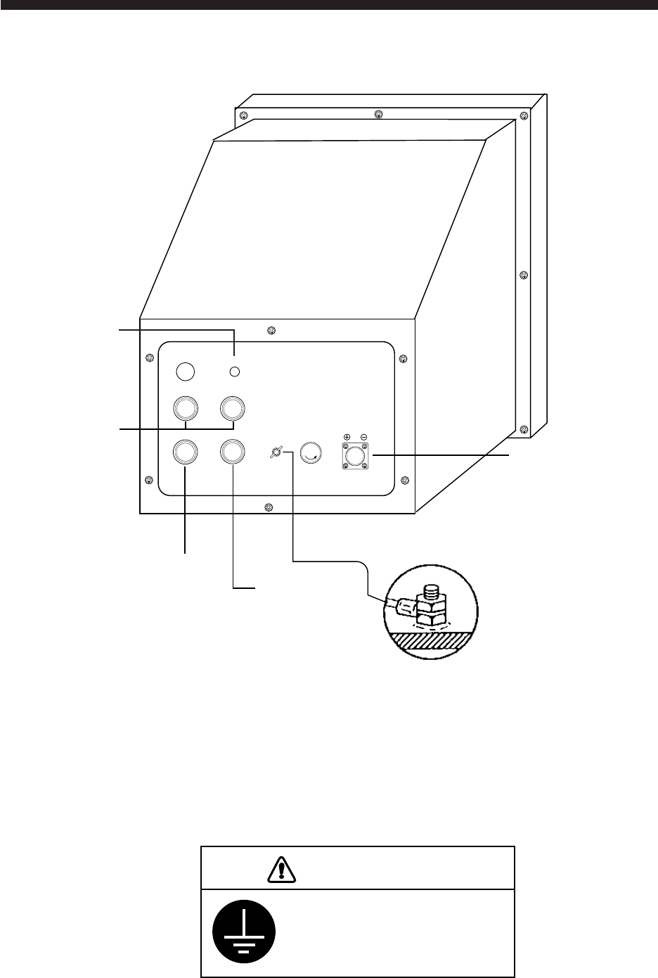
The figure below shows the location of connectors at the rear
of the display unit.
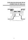
AP IN/OUT
ANT
DATA IN/OUT
FUSE 5A
12-24 VDC
DGPS
Autopilot
Ship’s Mains
White (+)
Black (-)
DGPS
Beacon
Receiver
DATA OUT
External
Equipment
Antenna
Ground
Figure 6 Wiring
Grounding
The display unit contains CPU circuits that radiate noise, which
can interfere with other radio equipment. Ground the unit to
prevent mutual interference.
Ground the equipment to
prevent mutual interference.
CAUTION