


P/N: 4FM020-010
© 2003 Vortech Engineering, LLC
All Rights Reserved. Intl. Copr. Secured
20OCT03
v3.1 4.6/5.4Exped/Nav(4FM v3.1)
18
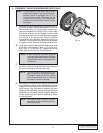
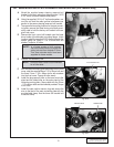
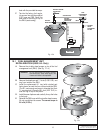
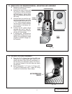
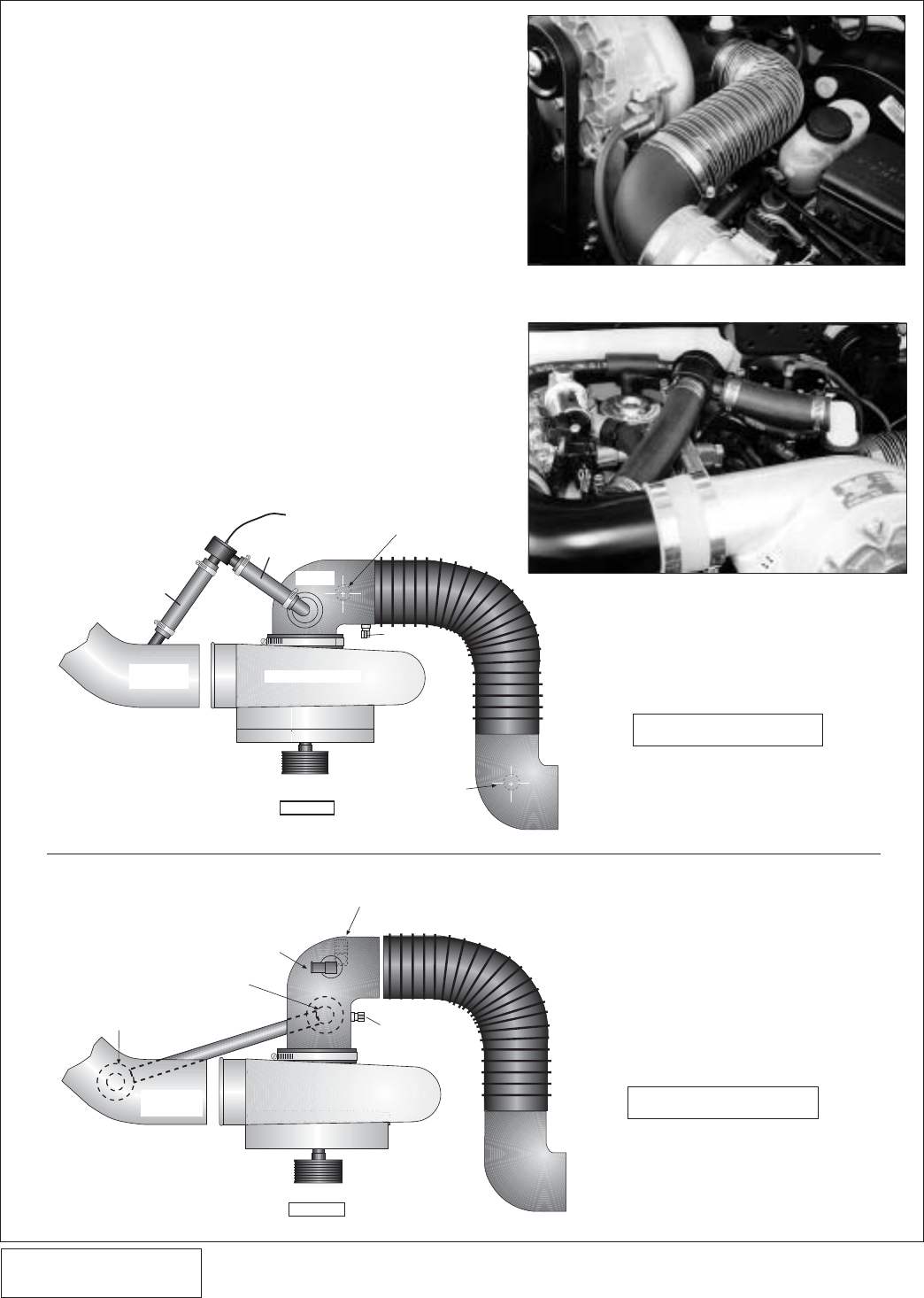
14. AIR INLET/BYPASS ASSEMBLY, cont'd.
C. Install the bypass valve and #16 hose clamp on the
end of the 1" x 5" hose - 4.6L, 1" x 9" hose - 5.4L. On
the 4.6L, bypass nipple should be pointing toward the
driver's seat. On the 5.4L, bypass nipple should be
pointing downward.
D. Using the supplied 5/32" TEE and hose, splice the by-
pass nipple into the previously installed vacuum hose
attached to the FMU lid.
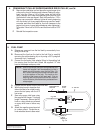
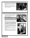
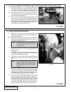
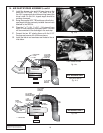
E. Place the 1" x 7"-4.6L, 1" x 2.5" - 5.4L piece of hose
and #16 hose clamps on the bypass valve. The hose
will be connected to the discharge in the next step.
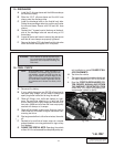
F. Connect the two 90° plastic elbows with the 3-1/2"
flex hose and secure with #56 hose clamps.
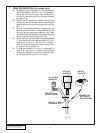
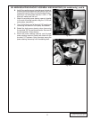
G. Install the idle air and crankcase vent hoses to the air
inlet elbow.
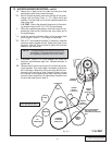
3/4” 90° BARB
TO IDLE AIR
RESONATOR
5/8” 90° BARB
DRIVER’S SIDE
VALVE COVER
CRANK VENT
FLEX
HOSE
1” x 5” HOSE
SUPERCHARGER
DISCHARGE
TUBE
1” x 7” HOSE
AIR INTAKE
TEMP SENSOR
VACUUM HOSE
TO FMU
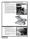
TOP VIEW
3-1/2" x 90°
ELBOW
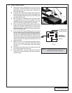
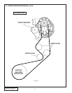
5.4L MODELS ONLY
4.6L MODELS ONLY
3/4” 90° BARB
TO IDLE AIR
RESONATOR
1” x 9” HOSE
DISCHARGE
TUBE
AIR INTAKE
TEMP SENSOR
TOP VIEW
SUPERCHARGER
----- = BOTTOM VIEW
BYPASS
VALVE WITH
1” x 2.5” HOSE
5/8” 90° BARB
DRIVERS SIDE VALVE
COVER CRANK VENT
1” X 90°
PLASTIC
HOSE BARB
FLEX
HOSE
4.6L model shown
(see photo above)
Fig. 14-b
Fig. 14-c
Fig. 14-d
Fig. 14-e