


P/N: 4FM020-010
© 2003 Vortech Engineering, LLC
All Rights Reserved. Intl. Copr. Secured
20OCT03
v3.1 4.6/5.4Exped/Nav(4FM v3.1)
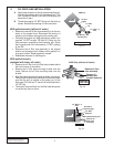
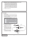
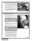
A. To prepare the mounting location for the main mount-
ing plate, remove the three 10mm factory stud/bolts
located on the driver side engine front cover.
B. Reinstall the accessory belt.
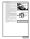
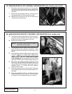
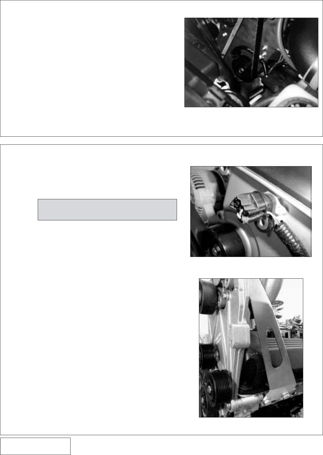
C. Cut and extend the cam sensor wires using the sup-
plied 18GA wires and solderless connectors. Using
tie wraps secure the cam sensor wire as shown in the
photo.
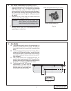
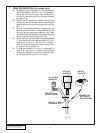
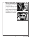
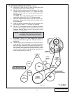
D. Install the large support bracket onto the engine block
using the 14mm x 2.0 x 35mm bolts, washers, and
spacers.
NOTE: The most forward mounting boss
should use the 14mm x 2.0 x 30mm and the smaller
of the two spacers.
(Do not tighten the bolts until the
upper part of the support bracket has been mounted.)
E. With the main mounting bracket positioned on the
front cover, (ensure that the cam sensor wire is not
being pinched by the mounting bracket) start the three
supplied 10mm x 1.5 x 80mm bolts with washers.
Torque all bolts evenly.
F. Secure the upper portion of the bracket to the previ-
ously installed support bracket using the supplied 1/4"
hardware.
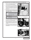
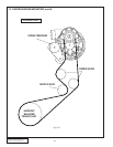
G. Using the supplied 7/16-14 x 1.5" bolts and dust
shields, secure the three (3) idlers to the main mount-
ing bracket in the configuration shown on page 15.
8A. MAIN MOUNTING PLATE ASSEMBLY AND MOUNTING (4.6L models only) cont'd.
10
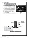
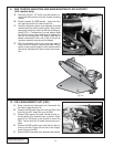
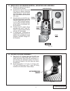
I. Move the power steering reservoir into the appropri-
ate location on the new power steering reservoir/coil
mounting bracket and secure with the provided 1/4"
hardware.
J. Secure the power steering reservoir lines away from
the steering shaft with the tie wraps provided.
K. Reattach the plug wires to the coil and secure with
the previously removed clips.
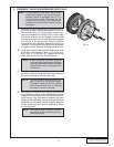
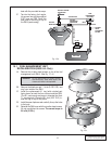
8B. MAIN MOUNTING BRACKET ASSEMBLY AND MOUNTING (5.4L models only)
NOTE: The use of blue Loctite is recom-
mended for all idler bolts.
Fig. 8B-a
Fig. 8B-b
Fig. 8A-d