


© Copyright Ford 2007
HM02 E 11464842 004
SK7S7J 19D520 PB
2/29
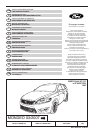
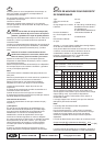
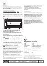
FITTING INSTRUCTIONS TOW BAR
Type: 307 317
D-value: 11.6 kN
Vertical load: ➜ 1/08 80 kg; 02/08 ➜ 90 kg
Manufacturer: Westfalia Automotive GmbH
Am Sandberg 45
D-33378 Rheda-Wiedenbrück
Area of use: Ford Mondeo 03/2007 ➜
EC-Type Approval No.: e13*94/20*2231
Official designation: BA7
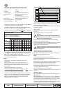
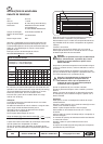
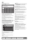
Important: The maximum vertical load (80 or 90 kg) depends
on the date of manufacture of the vehicle.
The date of manufacture of the vehicle can be determined
using the vehicle ID number and the table below.
Example: vehicle ID no. WF0GXXGBWS8B
23233 = Jan./2008
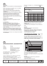
Identification table
Date of manufacture: year/month
Place 11 = year of manufacture
Place 12 = month of manufacture
Month
Year 01 02 03 04 05 06 07 08 09 10 11 12
6 = 2006 L Y S T J U M P B R A G
7 = 2007 C K D E L Y S T J U M P
8 = 2008 B R A G C K D E L Y S T
9 = 2009 J U M P B R A G C K D E
A = 2010 L Y S T J U M P B R A G
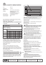
In case of vehicles with date of manufacture inclusive
Jan./2008, the enclosed vertical load sticker (max. 80 kg)
must be placed close to the trailer hitch or on the inside of
the boot in a position which is easily seen.
For vehicles manufactured from Feb./2008 onwards, the
max. vertical load is 90 kg.
Note:
Fitting is to be executed in accordance with these
instructions.
When using the trailer hitch, always observe the
manufacturer's data regarding trailer load and vertical
load. The figures stated for the trailer hitch must not
be exceeded.
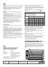
Formula for ascertainment of D-value:
The maximum permissible combined weight of vehicle and
trailer must not be exceeded. The maximum permissible
weight for the car-trailer combination is stated on the
vehicle's identification plate. Your Ford dealer will be
pleased to help you if required.
GB
Before using the coupling device, the correct trailer
electrical kit must be installed.
It is recommended to install the electrical kit before fitting
the trailer coupling.
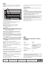
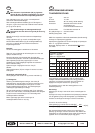
Raise vehicle.
Remove rear bumper (X1) and impact absorber as per
manual.
The impact absorber is no longer needed.
Caution:
Screw the bolts of the impact absorber (X2) and
also bolt (E) into the threads in the rear panel and
tighten to the specified torque.
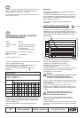
Detach exhaust muffler as illustrated and remove heat
shields as per workshop manual.
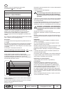
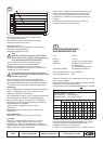
Push the side parts of the trailer coupling (A) into the holes
in the side rails and screw up handtight with tension
brackets (2x C) and bolts (6x D).
Caution: The trailer coupling must be bolted to the
bodywork with bolts and screw threads free from
oil and grease.
Tighten bolts (D) to the specified torque.
Replace exhaust muffler and heat shields.
Fit socket bracket (H) to trailer coupling (A), as illustrated,
and tighten to the specified torque.
Note:
At this point finish installing the electrical kit.
Using the template (S), cut out the middle section of the
bumper, as illustrated.
Replace rear bumper. Replace or tighten all parts removed
or loosened in accordance with workshop manual.
Insert ball neck (B) or plug (R) into the pilot tube.
Instructions for using the removable ball neck are given in
the User's Manual of the Vehicle.
Store the ballneck in the trunk as shown.
The socket bracket (H) can be swung to the left under the
bumper.
Operating notes:
The coupling ball must be kept clean and well greased (*).
(*) Exception:
When stabilisers are in use which act on the coupling ball,
pro-ceed according to the instructions of the manufacturer
of the stabilisers. When stabilisers are in use, the coupling
ball must be inspected for wear at regular intervals.
As soon as a coupling ball diameter of 49.0 mm or smaller
has been reached at any point, the towing device
XXXX kg
Trailer mass [kg] x gross vehicle mass [kg] 9,81
Trailer mass [kg] + gross vehicle mass [kg] 1000
x
= D [kN]
!
!