


Installation Considerations 3-9
Section 3: Installation Considerations
Driver/passenger air bags affect the way police equipment can be mounted in police vehicles. Any
surfaces that could come into contact with an air bag during deployment must not damage the air
bag or alter its deployment path. Sharp edges, corners or protrusions could damage the nylon air
bag material and reduce the effectiveness of the air bag. Do not mount or place any objects in the
deployment path of an air bag. Air bags must be allowed to fully deploy without restriction. The
deployment of air bags is not compatible with any configuration of police equipment mounting that
places objects in the air bag deployment path. Equipment mounted or placed in the deployment
area of an air bag will reduce the effectiveness of the air bag, damage the air bag and potentially
damage or dislodge the equipment.
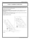
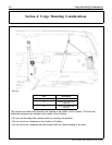
Air bag deployment drawings are provided in Section 5: Reference Information. Consult the
drawings before equipment is installed inside the passenger compartment to make sure that the
mounted equipment does not interfere with air bag deployment.
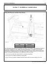
Seat Bolts
NOTICE: Do not install longer seat bolts if reinstalling seats.
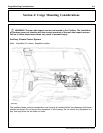
The vehicle safety belts and seat assemblies are factory installed in their correct location. Seat
attaching bolts are not to be used as attachment points for any equipment. Any added material
between the seat bolt and the seat frame could have unpredictable effects on the seat bolt torque.
If the safety belts are removed for any reason, all of the appropriate attaching hardware must be
hand started and then tightened to the correct torque specifications as per the workshop manual.
Correct operation must be verified before returning the vehicle to service.
Driveshaft Clearance
When installing police equipment such as a console or other equipment in the console area, it is
important to consider the available clearance between the underbody and the driveshaft. Never
use self-tapping screws and never use screws that are longer than necessary in the console area.
Brake Line Clearance
When installing equipment, it is important to consider the available clearance between the brake
lines and the fastener or component. Any fasteners or static components should allow a minimum
of 15 mm (0.60 in) clearance to the brake lines. Any dynamic components should allow for a
minimum of 19 mm (0.75 in) clearance to the brake lines.
Battery Saver
All Expedition vehicles are equipped with a battery saver feature, which is a function of the smart
junction box (SJB). The battery saver will disrupt power to the courtesy, demand and headlamps
off after 10 minutes, and chimes after 30 minutes. Interior lamps include the dome lamps and the
instrument cluster lamps. Demand lamps include the front map lamp, glove compartment lamp,
luggage compartment lamp and engine compartment lamp. Turning the ignition switch to the RUN
or ACC position will terminate the battery saver feature by disabling the interrupt timers, reinstating
power to the lamps.
2010 Expedition SSV Modifiers Guide, 07/2009