


Electrical 2-7
Section 2: Electrical
• Determine the terminal type. Base your decision on wire gauge, current carrying capacity,
connector type and insulation type.
— Use non-detent low insertion force terminals whenever possible.
— Do not use low insertion force female terminals in weather-resistant connectors.
— Analyze circuit requirements (signal levels, current, voltage) to determine the correct plating
material (such as gold). Use of non-plated terminals is not recommended.
— Do not use plugs to seal holes in micropin connector grommets. It is very easy to forget to
insert them during manufacturing and ruin the seal. Use a grommet with only the necessary
number of holes or use dummy wires at least 600 mm (24 in) long.
— Fully align connectors prior to terminal connection — terminal cavities should have minimum
tolerance to prevent terminals from floating, bending or pin push-out during
mating/engagement.
— Make sure connectors of similar type and color are identifiable to the operator to eliminate
crossed connections and minimize assembly time. Avoid using similar types and colors of
connectors close together.
— Be sure that connectors have positive locking devices that allow easy installation with a low
insertion force and easy removal. The connector snap should be easily felt and heard.
— Eliminate the use of edgeboard, tang-type and molded-over connectors. The use of
blade-type weather-resistant connectors is restricted to high-current applications which cannot
be handled by submersible connectors.
Circuit Protection and Electrical Load
• Modification to existing vehicle wiring should be done only with caution and careful consideration
of effects on the completed vehicle electrical system. Anticipated circuitry should be studied to
determine the required circuit protection and to avoid feedback loops.
• Added circuitry must be protected either by a base vehicle fuse or circuit breaker, or by a similar
device supplied by the modifier.
• When adding loads to a base vehicle-protected circuit, make sure that the total electrical load
through the base vehicle fuse or circuit breaker is less than the device’s load rating.
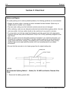
• Use 80% of the fuse rating to determine maximum steady state load to reduce nuisance fuse
failures.
2010 Expedition SSV Modifiers Guide, 07/2009