


1077 Actuator
Instruction Manual
Form 5605
March 2007
5
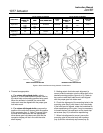
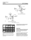
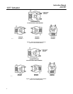
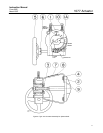
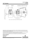
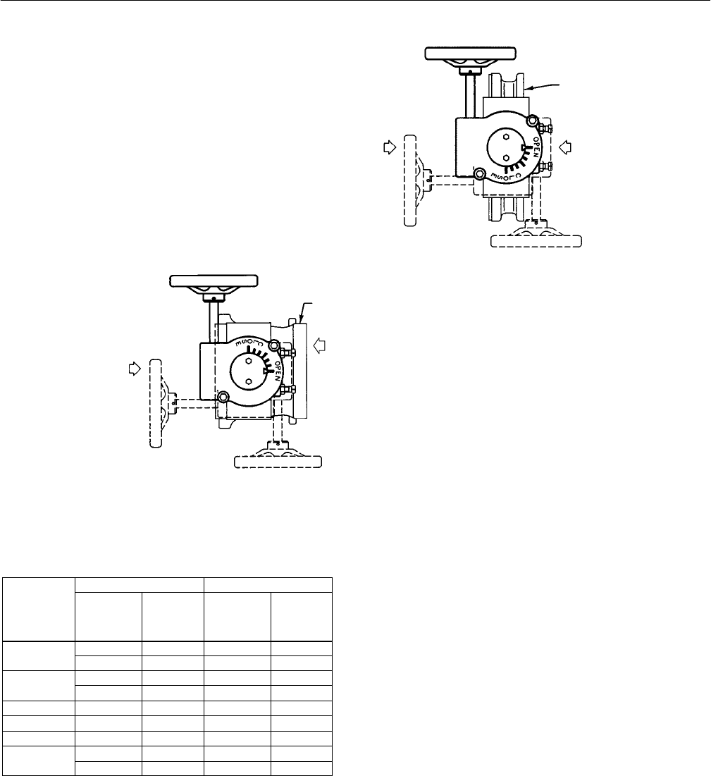
Figure 3. Available Mounting Positions
30B0668-A
B2002-3 / IL
DIRECT ACTING ACTUATOR CONSTRUCTION
REVERSE ACTING ACTUATOR CONSTRUCTION
FLOW DIRECTION
FOR LEFT-HAND
MOUNTING
POSITION 3
POSITION 1
POSITION 4
FLOW
DIRECTION FOR
RIGHT-HAND
MOUNTING
FLOW DIRECTION
FOR
LEFT-HAND
MOUNTING
VALVE BODY
FLOW
DIRECTION FOR
RIGHT-HAND
MOUNTING
POSITION 1
POSITION 3
VALVE BODY
POSITION 4
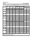
Table 3. Approximate Weights
METRIC UNITS U.S. UNITS
ACTUATOR
SIZE
Handwheel
Diameter,
mm
Weight of
Actuator
Assembly,
Kg
Handwheel
Diameter,
Inches
Weight of
Actuator
Assembly,
Pounds
0-KE
152 3.7 6 8
0-KE
203 4.7 8 10
2-KE
203 10.3 8 22
2-KE
305 11.3 12 24
6-KE 610 20.2 24 43
7-KE 762 28.2 30 60
9-KE 914 40.9 36 87
10-KE:6
432 62.6 16 133
10-KE:6
610 62.6 24 133
8. If removed for inspection, install the gearbox
cover plate. For a size 0-KE actuator only, also
install the O-ring onto the hub of the drive sleeve
gear.
9. Making certain that the travel indicator pointer is
aligned as it was prior to disassembly, install the
travel indicator.
10. Before installing the valve body and actuator in
the pipeline, perform the procedures presented in
the Adjustment section of this manual.
Adjustment
Perform the following steps to adjust the travel stops
and the travel indicator pointer. Individual part key
numbers and part descriptions referenced in this
procedure are shown in figure 6 except where
otherwise indicated.
Travel stops (key 10) consist of two set screws and
two hex nuts. For 90-degree valve disc or ball
rotation, both set screws are of equal length. For
60-degree disc or ball rotation, one set screw is
longer than the other. To change from 90-degree to
60-degree disc or ball rotation, one set screw must
be replaced with a longer one as explained below.