


1077 Actuator
Instruction Manual
Form 5605
March 2007
4
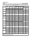
VALVE SERIES OR DESIGN VALVE SERIES OR DESIGN
MOUNTING
Ball/Plug
Rotation To
V250
V150 V200 & V300
CV500
Disc/Ball
Rotation To
V250
8532, 8560
MOUNTING
Rotation To
Close
V250 V150, V200 & V300
CV500
V500
Rotation To
Close
V250
8532
,
8560
& 9500
Right-Hand
CCW
(2)
CCW
REVERSE REVERSE REVERSE
CW
CW
NA
NA
DIRECT
Left-Hand
CCW
CCW
NA
NA
REVERSE REVERSE
CW
CW
DIRECT DIRECT
Left-Hand
(Optional)
(1)
CW
(3)
CW
NA
NA
DIRECT
NA
NA
NA
NA
NA
NA
NA
NA
1. A left hand ball will be required for the NPS 3 through 12 Series B and the NPS 14 to 20, with or without attenuator.
2. Counterclockwise
3. Clockwise
40B1561–A / DOC
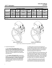
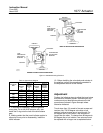
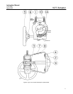
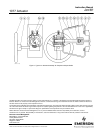
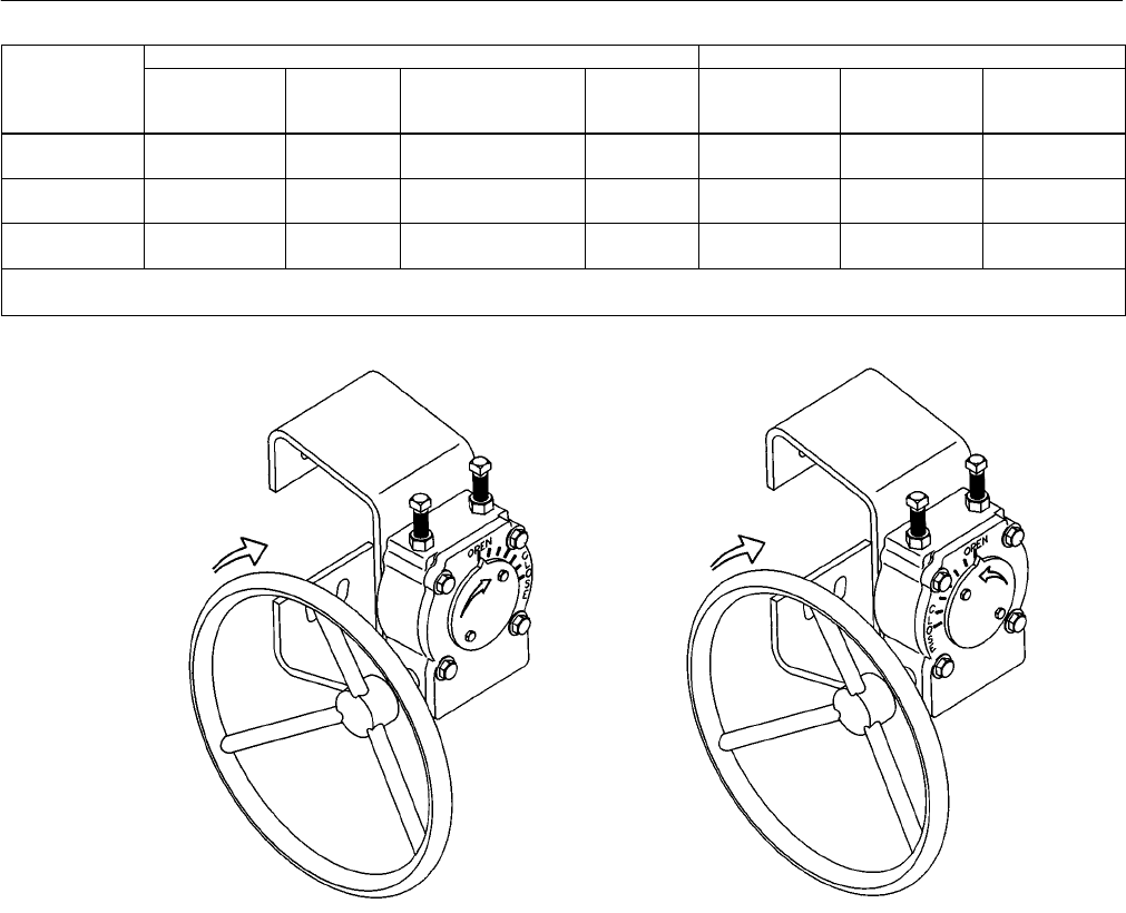
DIRECT ACTING CONSTRUCTION REVERSE ACTING CONSTRUCTION
Figure 2. Direct and Reverse Acting Actuator Constructions
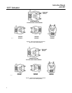
4. Proceed as appropriate:
a. For valves with splined shafts, refer to
figures 3, 4, and 5 and locate the correct view for
the valve body and mounting position being used.
When the actuator is installed, the valve shaft
index mark must be aligned with the proper gear
hub index mark.
b. For valves with keyed shafts, compare the
position of the stub shaft keyway with the position
of the connector (key 11, figure 7) keyway. Align
the stub shaft index mark with the appropriate
drive sleeve gear hub index mark such that the
connector keyway will be in line with the valve
shaft keyway.
5. Making certain that index mark alignment is
correct, slide the actuator onto the valve shaft in the
desired mounting position (figure 4 or 5). Check to
be sure the valve shaft index mark is still aligned
with the proper gear hub index mark.
6. Check the alignment of the mounting holes in the
mounting yoke (key 2) with those in the valve body.
If the holes are not aligned, rotate the handwheel to
allow repositioning of the yoke. It may be necessary
to loosen the hex nuts and back out the travel stop
set screws (key 10) to allow this repositioning.
7. When hole alignment is correct, secure the
mounting yoke to the valve body with washers
(key 4) and the valve body cap screws (key 9).