


OPERATION AND SERVICE INFORMATION
Page 24
Owner’s Manual and Service Guide
Read all of manual to become thoroughly familiar with this vehicle. Pay particular attention to all Notes, Cautions and Warnings
WHEELS AND TIRES
Tires are uni-directional and should never be
moved from one side of vehicle to the other.
This vehicle comes standard with low pressure, tubeless,
uni-directional tires mounted on one piece wheels (Ref.
Fig. 34 on page 24). Left side tires should always remain
on left side of vehicle. Right side tires should always
remain on right side of vehicle. Uni-directional tires have
an arrow on their sidewall indicating direction of rotation
when moving forward.
TIRE INSPECTION AND INFLATION
To reduce possibility of
severe injury or death
from tire separating from
wheel or exploding, use caution when inflating tires
and never exceed maximum pressure rating on side-
wall of tire. Overinflation can occur quickly.
Tire condition should be inspected per the PERIODIC
SERVICE SCHEDULE See ‘PERIODIC SERVICE
SCHEDULE’ on page 15. Examine for cuts, punctures
and excessive wear. Repair or replace as necessary.
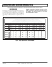
Air pressure should be checked when tires are cool. If air
needs to be added, see GENERAL SPECIFICATIONS
section of this manual. Standard and optional tires should
be inflated to pressure designated. If pressure is not des-
ignated, inflate to pressure recommended on sidewall of
tire. Under no condition should inflation pressure be
higher than maximum pressure listed on sidewall of tire.
All four tires should have the same pressure for opti-
mum handling characteristics.
Use caution when inflating tires. Due to low volume of
small tires, overinflation can occur in seconds. Overinfla-
tion could cause tire to separate from wheel or cause tire
to explode.
Be sure to install valve dust cap after checking.
REMOVAL AND INSTALLATION
To reduce possibility of
severe injury caused by
a broken socket when
removing wheels, use only sockets designed for
impact wrench use.
Hardware involved: 3/4" hex lug nut
To remove, loosen lug nuts. If using an impact wrench,
use only impact sockets with it. Regular sockets are not
designed for impact pressures exerted by power tools.
Raise vehicle. See LIFTING THE VEHICLE on page 17.
Remove lug nuts and wheel.
To reduce possibility of damage, tight-
en lug nuts to no more than 85 ft. lbs.
(115 Nm) torque.
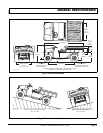
Use ‘cross sequence’ pattern when tightening
lug nuts to assure even seating of wheel
against hub.
Special Tools Required Qty.
Torque wrench, ft. lbs. .................................................1
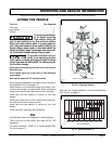
To install, place wheel onto studs with valve stem facing
away from hub (Ref. Fig. 34 on page 24). Be sure to
position wheel on hub correctly with arrow on tire indicat-
ing direction of rotation when moving forward.
Add lug nuts and finger tighten.
Secure wheel by tightening lug nuts in a ‘cross sequence’
pattern to 50 - 85 ft. lbs. (70 - 115 Nm) torque in 20 ft. lbs.
(30 Nm) increments.
Lower vehicle
.
! !
! !
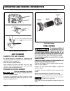
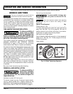
Fig. 34 Wheel Tightening Sequence
Tire style may vary
1
2
3
4
'Cross Sequence'
Front of
Vehicle
R
o
t
a
t
i
o
n
Ref Whi 4