


3024C Actuator
Instruction Manual
Form 5760
March 2007
5
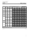
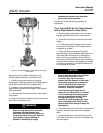
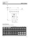
Table 4. Handwheel Specifications
ACTU-
ATOR
SIZE
HAND-
WHEEL
DIAMETER
TURNS PER
mm/INCH
TRAVEL
RIM
FORCE
(1,2)
HAND-
WHEEL
OUTPUT
FORCE
SIZE
mm In. mm In. N lb N lb
30 and
30E
200 7.87 0.24 6.1 179 40 5000 1125
34, 34E,
40, and
40E
250 9.84 0.21 5.4 286 64 10,000 2250
45 and
45E
250 9.84 0.21 5.5 400 90 14,000 3150
1. Tangential handwheel force required to produce the handwheel output force
shown.
2. Brass operating nut and stainless steel screw.
Installation
WARNING
Always wear protective gloves,
clothing, and eyewear when
performing any installation operation
to avoid personal injury.
Personal injury or equipment damage
caused by sudden release of pressure
may result if the actuator assembly is
installed where service conditions
could exceed the limits given in tables
1, 2, and 3 or the appropriate
nameplates. To avoid such injury or
damage, provide a relief valve for
overpressure protection as required by
accepted industry and governmental
codes and good engineering practices.
To avoid parts damage, do not use a
normal operating pressure that
exceeds the Maximum Diaphragm
Casing Pressure (see table 1) or
produces a force on the actuator stem
greater than the Maximum Allowable
Output Thrust (see table 2 or 3) or
Maximum Allowable Valve Stem Load.
Check with your process or safety
engineer for any additional measures
that must be taken to protect against
process media.
When ordered, the valve configuration
and construction materials were
selected to meet particular pressure,
temperature, pressure drop, and
controlled fluid conditions.
Responsibility for the safety of
process media and the compatibility of
valve materials with the process media
rests solely with the purchaser and
end user. Since some valve body/trim
materials combinations are limited in
their pressure drop and temperature
ranges, do not apply any other
conditions to the valve without first
contacting your Emerson Process
Management sales office.
If installing into an existing
application, also refer to the WARNING
at the beginning of the Maintenance
section in this instruction manual.
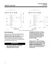
A Type 3024C diaphragm actuator is normally
shipped mounted on a valve. Refer to the
appropriate valve instruction manual when installing
the valve in the pipeline. If the actuator is shipped
separately or if it is necessary to mount the actuator
on the valve, perform the Actuator Mounting
procedure given below. For information on mounting
the positioner refer to the appropriate positioner
instruction manual.
CAUTION
The Type 3024C actuators are
designed to mount on push-down-
to-close valves. Do not mount these
actuators on any other type of valve
without first contacting your Emerson
Process Management sales office.
Mounting the Actuator on the Valve
The following procedure describes how to mount a
Type 3024C actuator on a push-down-to-close valve
so that the actuator stem and valve stem thread
engagement allows full travel and proper shut-off.
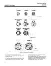
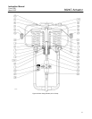
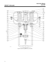
Refer to table 4 and figures 6 and 7 for actuator