


3024C Actuator
Instruction Manual
Form 5760
March 2007
13
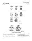
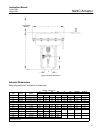
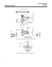
Figure 6. Actuator Dimensions
1Q57491
D
E
F
C
AR (ACTUATOR
REMOVAL)
D
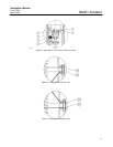
Actuator Dimensions
Refer to figures 6 and 7 and table 5 for dimensions.
Table 5. Dimensions
Actuator Valve Yoke Boss,
C E F
(1)
AR Js Hs M (ATO) M (ATC)
Actuator
Size
Valve
Travel
Yoke
Boss
,
Inches
Millimeters
30 16 mm 2-1/8 (54 mm) 215 370 140 105 205 280 185 80
34 16 mm 2-1/8 (54 mm) 315 400 140 105 250 280 185 80
40 32 mm 2-13/16 (71 mm) 315 420 170 133 250 280 210 100
45 32 mm 2-13/16 (71 mm) 420 450 170 133 250 280 210 100
Inches
30E 0.75 2-1/8 8.5 14.6 5.6 4.7 8.1 11.0 7.3 3.1
34E 0.75 2-1/8 12.4 15.8 5.6 4.7 9.8 11.0 7.3 3.1
40E 1.125 2-13/16 12.4 17.9 8.1 6.6 9.8 11.0 9.6 5.5
40E 1.5 2-13/16 12.4 18.9 8.3 6.6
---
---
---
---
40E 2 2-13/16 12.4 18.9 8.5 6.2
- - - - - - - - - - - -
45E 1.125 2-13/16 16.5 19.3 8.1 6.6 9.8 11.0 9.6 5.5
45E 1.5 2-13/16 16.5 20.1 8.3 6.6
---
---
---
---
45E 2 2-13/16 16.5 20.1 8.5 6.2
- - - - - - - - - - - -
1. This is the distance between the base of the yoke to the centre of the stem connector at the fully-up postion. This ensures the positioner feedback arm, if fitted, is
horizontal at mid-travel.