


7
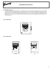
Installation Instructions
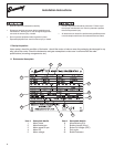
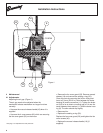
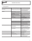
4.2 Disassembly and reassembly of the brake
manual release (default option) (Figure 2)
Disassembly of the brake manual release:
• Unscrewthehandle(16)ofthemanualrelease(14)
(if supplied).
• Removethefancoverscrews(40)whichare
securing the fan cover (23) in place.
• Removethetwoscrews(12)onthemanualrelease
(14) and release the spring (13).
• Removethemanualrelease(14).
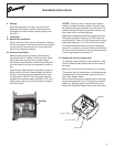
Reassembling the brake manual release:
• Positionthebrakemanualrelease(14)aroundthe
brake housing (8).
• Installscrew(12)onthelefttoafxthemanual
release (14).
• Installscrew(12)withspringonrightwithlargeend
of spring engaged into hole in housing (8) (see Figure
2). Tighten screw (12). Once screw is tightened, set
short end of spring under manual release notch (see
Figure 2).
• Assemblethefancoverguard(23)withscrews(40).
• Removetherubberpluginthefanguardand
assemble the handle (16) (if required) to release the
brake manually.
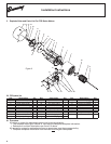
4.3 Changing brakemotor on modular gear
Removing brakemotor from gear:
• Removefancoverguard(23)frommotor.
• Removebrakenut(24)whileholdingfan(15
stationary. Remove washer (20).
• Disassemblemanualreleaseper4.2above.
• Removethemotorstudnut(25)andmotorstud
(61).
• Usebearingpullertoremovefan(15)andbrake
armature (11) together.
• Follow"ModularMotorDisassembly"instructions,
which are supplied with the replacement brakemotor,
to now remove the motor rotor and stator.
Reinstalling new brakemotor onto gear with
modular tapered input connection:
• Clean female taper of new motor's shaft completely
with petroleum solvent.
NOTICE: Do not lubricate the female taper end of the
motor shaft or the male taper of the reducer shaft.
Lubrication could cause the connection to slip in
service
• Keeping rotor (2) and stator (1) together, rotate
rotor/brake until pair of tapped holes in brake housing
(8) are at 90 degrees from where manual release
handle (16) is desired.
• Install the 4 stator bolts (5) through brake housing
(8) and stator assembly and engage them into gear
input bracket. Tighten in alternating rotating pattern.
• Install and tighten rotor stud nut per "Modular Motor
Assembly" instructions supplied with replacement
brakemotor.
• Hold brake fan with an adjustable wrench to prevent
rotation, insert 0.4 mm shim between brake housing
(8) and armature plate (11). Tighten brake nut (24) to
just before shim is captive but less than .50 mm shim.
• Replace the sealing o-ring (50).
• Reassemble the brake manual release components
per 4.2 above if required to original orientation.
• Assemble the brake fan cover guard (23) using 4
screws (40).
• Replace manual release handle (16) (if required).
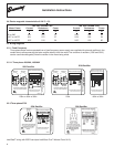
4.4 Braking torque (ft. lbs.)
The table below defines the standard braking torque
rating for the FCR brakemotor or gearmotor designs:
Figure 2
Motor
Frame
Brake Rating Springs
HP / Poles (FT. Lbs.) Qty and Color
0.33 HP / 4 56/56C 2.2 4 blue
0.50 HP / 4 56/56C 2.5 6 blue
0.75 HP / 4 56/56C 4.4 3 green
1.00 HP / 4 143T/56C/143TC 5.9 4 green
1.50 HP / 4 145T/145TC 7.4 5 green
2.00 HP / 4 145T/145TC 8.85 6 green
3.00 HP / 4 182T/182TC 15 4 grey
5.00 HP / 4 184T/184TC 23 5 grey
16
13
12 and 13
14
12
12 and 13
Manual
Release
Notch
Hole in
Housing (8)