


4
Installation Instructions
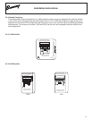
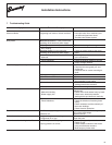
3.5 Wiring diagrams
3.4 Electro-magnetic characteristics @ 20°C + 5%
IntelliGear
®
wiring with ESFR card (see IntelliGear Plus™ Manual Form 9112).
SO6 Rectifier
SO8 Rectifier
230v or 460v or 380v
460v or 380v
230v
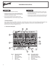
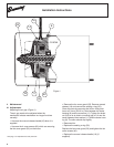
Three phase brake motors operated from a fixed frequency power supply are supplied with onboard rectifiers in the
conduit box to allow powering the brake rectifier directly from the motor. Two versions of rectifiers ( SO6 and SO8 )
can be used interchangeably. Note the rectifier in the motor being wired.
3.5.1 Fixed Frequency
3.5.1.1 Three phase 230/460, 190/380V
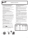
3.5.3 Three phase 575V
~
~
_
-
+
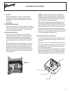
(A) Break DC: faster response time.
Remove jumper and add contact.
180V DC
230V AC
(A)
B2B1
+
-
15%
T2 T3
T1
B1
B2
*S06 Brake
Rectifier
CAUTION: DISCONNECT THE RECTIFIER CELL WHEN
TESTING FOR CURRENT INSULATION OR DIELECTRIC.
C
LR57008
*Disconnect B1 and B2 for separate
power supply to Brake Rectifier (S06)
Insulate ends of B1 and B2 if
separate power supply used
for Brake.
!
Brake Connection Diagram
Single Voltage
IMPORTANT
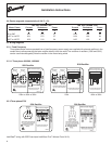
SO6 Rectifier
FN0419
SO6 Rectifier
SO8 Rectifier
*Disconnect B1 and B2 for separate
power supply to Brake Rectifier (S06)
T4 T5 T6
T7 T8 T9
T1 T2 T3
B1 B2
T4 T5 T6
T7 T8 T9
T1 T2 T3
B1 B2
*S06 Brake
Rectifier
*S06 Brake
Rectifier
C
LR57008
~
~
_
-
+
CAUTION: DISCONNECT THE RECTIFIER CELL WHEN
TESTING FOR CURRENT INSULATION OR DIELECTRIC.
(A) Break DC: faster response time.
Remove jumper and add contact.
180V DC
230V AC
(A)
B2
B1
+
-
15%
380/460V AC
180V DC
SO6 Rectifier
IMPORTANT
Brake Connection Diagram
FN0416
Lo-Volts
HI-Volts
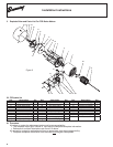
*Disconnect B1 and B2 for separate
power supply to Brake Rectifier (S08)
T4 T5 T6
T7 T8 T9
T1 T2 T3
B1 B2
T4 T5 T6
T7 T8 T9
T1 T2 T3
B1 B2
*S08 Brake
Rectifier
*S08 Brake
Rectifier
C
LR57008
~
~
_
+
-
++
CAUTION: DISCONNECT THE RECTIFIER CELL WHEN
TESTING FOR CURRENT INSULATION OR DIELECTRIC.
(A) Break DC: faster response time.
Remove jumper and add contact.
180V DC
(A)
B2
B1
+
-
15%
IMPORTANT
Brake Connection Diagram
Lo-Volts
HI-Volts
230V AC
SO8 Rectifier
~
~
_
+
-
++
(A) Break DC: faster response time.
Remove jumper and add contact.
(A)
+
-
15%
380/460V AC
180V DC
Brake Connection Diagram
Separate Power Supply Required
SO8 Rectifier
180 VDC Brake Coil 100 VDC Brake Coil
Motor Frame Current Resistance Power Current Resistance Power
A Ω W A Ω W
56 or 56C 0.31 572 57 0.54 186 54
140T or 140TC 0.31 572 57 0.54 186 54
180T or 180TC 0.35 510 64 0.65 155 65