


5
Installation Instructions
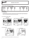
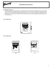
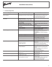
Three phase brake motors operated from a variable frequency power supply are designed with onboard rectifiers
in the conduit box to allow powering the brake rectifier from a 115V or 230V fixed frequency single phase power
separate from the motor/VFD but interlocked with that power source such that both motor and brake get powered
simultaneously. Two versions of rectifiers ( SO6 and SO8 ) can be use inter-changeably. Note the rectifier in the
motor being wired.
3.5.2 Variable Frequency
C
LR57008
~
~
_
-
+
I
M
PORTANT
CA UT
IO
N: DISC ON
NECT THE R E
CTIF
IER CELL WHEN
TES T
ING FOR
CURR E NT INS UL A
T
ION OR DIE L EC T
R IC.
100V DC
115V AC
(A)
+
-
15%
230V AC
100V DC
Brake Connection Diagram
Separate Power Supply Required
SO6 Rectifier
FN0438
(A) Break DC: faster response time.
Remove jumper and add contact.
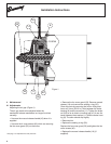
3.5.2.1 SO6 Rectifier
3.5.2.2 SO8 Rectifier
115V
~
~
_
+
-
++
100V DC
115V AC
(A)
+
-
15%
(A) Break DC: faster response time.
Remove jumper and add contact.
SO8 Rectifier
Brake Connection Diagram
Separate Power Supply Required
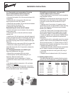
230V 115V
230V
~
~
_
+
-
++
(A)
+
-
15%
230V AC
100V DC
Brake Connection Diagram
Separate Power Supply Required
SO8 Rectifier
(A) Break DC: faster response time.
Remove jumper and add contact.