


3
2 Storage
Store the equipment in a clean, dry place that is
protected from shocks, vibration and temperature
fluctuations and with relative humidity levels of less
than 90%.
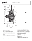
3 Installation
3.1 Mechanical Installation
Allow a minimum of 8.3 inches of clearance between
the fan cover guard of the brakemotor and any surface
to allow room for removing the fan cover guard and
servicing or adjusting the brake.
3.2 Electrical Installation
Make all electrical and grounding connections in
accordance with all national, and local codes. When
these motors are supplied with normally closed
thermostats, they should be wired to the holding coil
of a motor starter and are not designed for power in-
put.
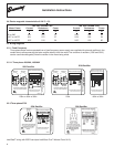
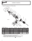
Power Supply (see connection diagrams on page 4)
Brake motors with built-in power supply can be con-
nected in the same way as a standard motor. They
are fitted with a 180V DC coil. The brake is directly
supplied from the motor stator (230/460, 575V) via a
brake power supply unit with the rectifier mounted in
the terminal box.
NOTICE: When the motor is started with reduced
voltage or variable frequency power, the brake must
be supplied with power separate from the motor. The
reduced voltage will likely not release the brake, and
thus cause motor and brake damage.
Brakemotors designed specifically for operation from
VFD power sources will have a 100 VDC brake coil
and the rectifier. These 100 VDC brakes require a sep-
arate fixed frequency 115 or 230 VAC power source.
For shorter brakes set times to prevent coasting po-
tentials, it's necessary to use an auxiliary contact from
the motor start and connect it to the rectifier as shown
in the wiring diagrams as location "A".
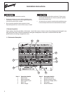
3.3 Brakes with manual release lever
To manually release the brake, exert pressure on the
manual release handle towards the non-drive end of
the motor.
Make sure to re-set it after maintenance is complete.
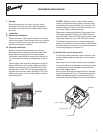
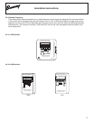
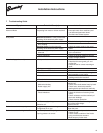
The terminal box on a brakemotor or brake gearmotor
is supplied with two (2) threaded openings on side 1
and 3. See diagram below.
Each of these openings are supplied with a threaded
plug allowing removal of any or all plugs for required
cable entry. Keeping plugs in unused locations pre-
serves the enclosure integrity of the motor and brake.
Installation Instructions
(2) 3/4-14 NP
T
(2) 1/2-14 NPT
Side 3
Side 1
Rectifier