


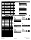
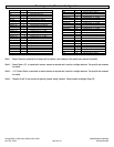


Connector J2 Pin Function
Gnd 1 System ground, (Note 1)
Channel 17 2 Analog Sensor, 0 - 10 VDC
Channel 18 3 Analog Sensor, 0 - 10 VDC
Channel 19 4 Analog Sensor, 0 - 10 VDC
Channel 20 5 Analog Sensor, 0 - 10 VDC
Channel 21 6 Analog Sensor, 0 - 10 VDC
Channel 22 7 Analog Sensor, 0 - 10 VDC
Channel 23 8 Analog Sensor, 0 - 10 VDC
Channel 24 9 Analog Sensor, 0 - 10 VDC
Channel 25 10 Analog Sensor, 0 - 10 VDC
Channel 26 11 Analog Sensor, 0 - 10 VDC
Channel 27 12 Analog Sensor, 0 - 10 VDC
Channel 28 13 Analog Sensor, 0 - 10 VDC
+12 V Out 14 +12 V Sensor Power, (Note 3)
+12 V Out 15 +12 V Sensor Power, (Note 3)
+5 V Out 16 +5 V Sensor Power, (Note 2)
+5 V Out 17 +5 V Sensor Power, (Note 2)
Channel 29 18 Analog Sensor, 0 - 10 VDC
Channel 30 19 Analog Sensor, 0 - 10 VDC
Channel 31 20 Analog Sensor, 0 - 10 VDC
Channel 32 21 Analog Sensor, 0 - 10 VDC
Gnd 22 System ground, (Note 1)
Gnd 23 System ground, (Note 1)
Page 42 of 44
Catalog #91001, 91003, 91004, 91005, 91007, 91009
Rev. 2/06 - RS/mc
©2006 Edelbrock Corporation
Brochure #63-0282
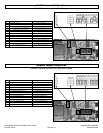
Connector J1 Pin Function
Tx 1 Serial Data To PC
Rx 2 Serial Data From PC
Battery 3 +12V System Power
Power Ground 4 System Power Ground
Ground 5 Sensor Ground, (Note 1)
+5 V Out 6 Sensor Power, +5V, (Note 2)
Channel 9 7 Accelorometer (Long) (Note 4)
Channel 10 8 Accelorometer (Lat) (Note 4)
Channel 11 9 Analog Sensor, 0 - 10 VDC
Channel 12 10 Analog Sensor, 0 - 10 VDC
Channel 13 11 Analog Sensor, 0 - 10 VDC
Channel 14 12 Analog Sensor, 0 - 10 VDC
Channel 15 13 Analog Sensor, 0 - 10 VDC
Channel 16 14 Analog Sensor, 0 - 10 VDC
Channel 1 15 Digital input 0 - 12 VDC
Channel 2 16 Digital input 0 - 12 VDC
Channel 3 17 Digital input 0 - 12 VDC
Channel 4 18 Digital input 0 - 12 VDC
Channel 5 19 Digital input 0 - 12 VDC
Channel 6 20 Digital input 0 - 12 VDC
+12 V Out 21 Sensor Power, +12V,, (Note 3)
Digital Out 1 22 0 or +5V (Off or ON)
Digital Out 2 23 0 or +5V (Off or ON)
Pin Assignments, Maximum Configuration
Note 1: Sensor Ground is connected to all sensor and is used as a zero reference: See specific user manuals for details
Note 2: Sensor Power +5V , is connected to various sensors as required and is used as a voltage reference. See specific user manuals
for details.
Note 3: +12 V Sensor Power is connected to various sensors as required and is used as a voltage reference. See specific user manuals
for details.
Note 4: Channels 9 and 10 may be used as general purpose analog channels. Reset jumpers accordingly (Page 45).