


Page 16 of 44
Catalog #91001, 91003, 91004, 91005, 91007, 91009
Rev. 2/06 - RS/mc
©2006 Edelbrock Corporation
Brochure #63-0282
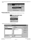
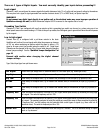
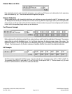
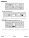
Channel Name and Units
Enter a descriptive name for each channel (this will appear on your graphs) e.g. Oil Pressure and an abbreviation for the engineering
units of the variable e.g. “psi”. These are the units that will appear on your graph.
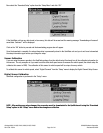
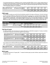
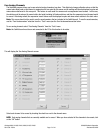
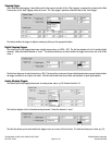
Channel Calibration
Analog channels have a six (6), element table that allows you to calibrate your sensor to provide the right EGT, oil pressure etc., read
out. Having 6 elements allows you to calibrate some non-linear sensors (e.g. NGK wide range oxygen sensor), but for most applications
(linear sensors), you will only need to utilize the left two elements. The lower numbers in gray are the raw voltage inputs, the numbers
in white are the corresponding display numbers you are interested in.
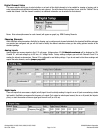
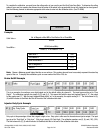
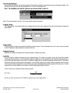
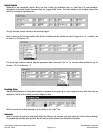
Fuel Pressure Example
Before entering in the calibration constants for an analog input you must find out the calibration of the sensor. The pressure
sensors that are sold with QwikData have a 1 to 5 volt linear output over the chosen pressure range of the sensor. The
default for Channel 11 is a 0 to 100-psi sensor. The calibration is thus (1)(0) (1-volt equals 0 psi) and (5)(100) (5 volts equals
100 psi). The third element is (0), (0) which indicates to QwikData that this is the end of the calibration table data.
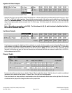
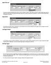
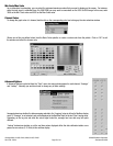
EGT Example
The EGT converters supplied with QwikData have an output of 0-10 volts over a temperature range of 32° to 1809°. F (0-987°. C).
The calibration is thus (0)(32) (0 volts equals 32°. F) and (10)(1809) (10 volts equals 1809°. F). The third element is (0), (0) which
indicates to QwikData that this is the end of the calibration table data.