


Page 12 of 44
Catalog #91001, 91003, 91004, 91005, 91007, 91009
Rev. 2/06 - RS/mc
©2006 Edelbrock Corporation
Brochure #63-0282
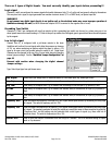
There are 3 types of Digital Inputs. You must correctly identify your inputs before proceeding!!!
Logic signal
Channels 1 and 6 are configured to measure signals that switch between a high (12 or 5 volts) and low (ground) voltage by themselves.
This may be a tach. signal, a signal generated from another electronic device (1TL or CMOS level), an injector input etc.
WARNING!!!
Do not connect any digital input directly to an ignition coil as the electrical noise may cause improper operation of
QwikData or damage the unit (Use MSD tachometer adapter #8132 to connect to the negative side of a coil).
Grounding Type Switch
Channels 2,3, and 5 are configured with a pull-up resistor so that a grounding type switch can be read, e.g. when using one of our
wheel speed sensors the normal reading is 12 V due to the pull-up resistor, then the signal goes to ground level when the switch passes
by the magnet.
Low to high signal
Channel Four (4), is configured with a pull-down resistor in the basic
QwikData unit to allow it to read signals with either the presence or absence
of 12V. e.g. when monitoring an ignition switch the signal is either a 12V
signal or an open circuit (not ground) when the switch is off. Digital Input
Channels can be changed to be any of the 3 types listed above by changing
internal jumper settings. See the
“QwikData Jumper Configuration”
on
page 43.
Proceed with caution when changing the digital channel
Jumper settings.
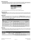
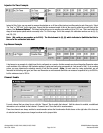
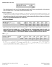
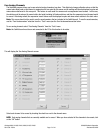
Type: Select Input type from pull-down menu.
Pure Digital Select when you simply want to .determine status of a two state input (e.g. Brake light on/off).
Duty High Used mostly for computer cars, E.g. to measure the percentage of time an input (e.g. injectors) is high.
Duty Low Used mostly for computer cars, E.g. to measure the percentage of time an input (e.g. injectors) is low.
On Time Used mostly for computer cars, E.g. to measure the absolute time (in milliseconds) an input (e.g. injectors) is
high.
Off Time Used mostly for computer cars, E.g. to measure the absolute time (in milliseconds) an input (e.g. injectors) is
low.
Frequency Rise Used to measure the frequency of an input (e.g. Tach, signal, wheel speed sensor) by measuring the rising edge
of a signal. The units for frequency are Hz x 100.
Frequency Fall Used to measure the frequency of an input (e.g. Tach. signal, wheel speed sensor) by measuring the falling edge
of a signal. The numbers generated by using this setting are usually the same as those measured by selecting
“Frequency Rise”, but this setting may be preferable with certain types of signals (e.g. those with lots of
electrical noise). The units for frequency are Hz x 100.
Counter Rise Used to count the number of transitions from low to high of a variable. This is an alternate setting for inputs
such as “lap beacons”.