


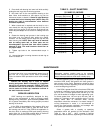
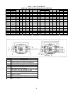
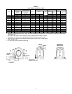
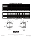
TABLE 8
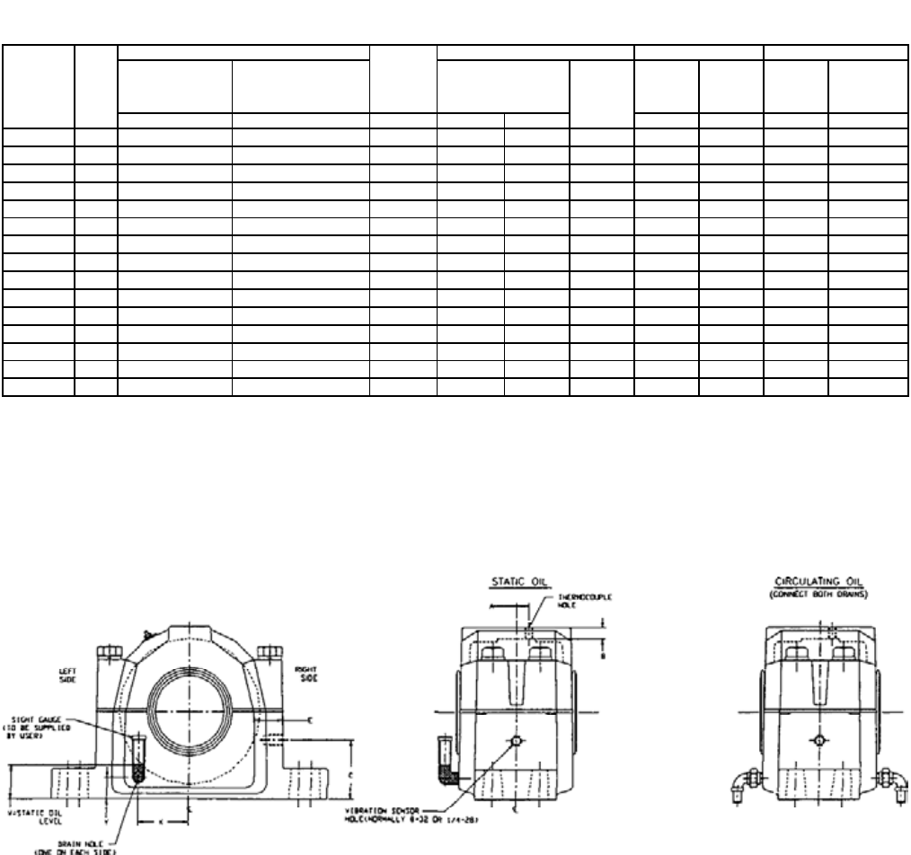
USAF CIRCULATING OIL CHART
CIRCULATING OIL FLOW* DRAIN HOLE, DRY SUMP*** THERMOCOUPLE HOLE VIBRATION SENSOR HOLE
BEARING
SEAT MM
HSG.
ERIES
AMOUNT SUFFICIENT
FOR NORMAL
LUBRICATION
MAXIMUM AMOUNT FOR
HEAT DISSIPATION
DUE TO EXTERNAL
HEAT SOURCE
STATIC OIL
LEVEL/IN.
LOCATION SIZE LOCATION
WALL
THICK.
LOCATION
WALL
THICK.
GAL/MIN. GAL./MIN. W** X Y A B C E
75 215 .0060 .175 1
5
/
32
1
25
/
32
7
/
8
¼–18
23
/
64
5
/
8
2¼ 1
3
/
16
80 216 .0065 .195 1¼ 1
31
/
32
61
/
64
¼–18
5
/
16
½ 2
9
/
32
1
33
/
64
85 217 .0075 .20 1
3
/
8
2
1
/
8
1
1
/
16
3
/
8
–18
13
/
32
43
/
64
2½ 1
7
/
16
90 218 .0080 .25 1
15
/
32
2¼ 1
1
/
8
3
/
8
–18
7
/
16
39
/
64
2
23
/
32
1
29
/
64
100 220 .011 .35 1
41
/
64
2
5
/
8
1¼
3
/
8
–18
17
/
32
45
/
64
3
5
/
64
1
43
/
64
110 222 .015 .42 1
51
/
64
2
7
/
8
1
11
/
32
3
/
8
–18
19
/
32
17
/
32
3
23
/
64
1
23
/
32
120 224 .0175 .48 1
27
/
32
3
3
/
16
1
3
/
8
½–14
11
/
16
49
/
64
3
3
/
8
1
55
/
64
130 226 .019 .55 2
11
/
32
3
5
/
16
1
5
/
8
½–14 ¾ 1" 4
1
/
32
2
5
/
32
140 228 .023 .60 2
1
/
32
3
5
/
8
1
15
/
32
½–14 ¾
57
/
64
4
1
/
32
2
5
/
32
150 230 .025 .75 2
1
/
32
3
19
/
32
1
23
/
64
½–14
13
/
16
7
/
8
4
11
/
32
2¼
160 232 .030 .80 2
3
/
32
4
1
/
32
1
21
/
64
½–14
29
/
32
59
/
64
4
33
/
64
2
7
/
32
170 234 .035 .85 2
3
/
16
4
5
/
32
1
21
/
64
½–14 1" 1
25
/
64
4
31
/
32
2
45
/
64
180 236 .037 .875 2
27
/
64
4
7
/
32
1
5
/
8
½–14 1" 1
21
/
64
5¼ 2¾
190 238 .039 1.0 2
17
/
32
4¾ 1
39
/
64
½–14
11
/
8
1¼ 5½ 3
3
/
32
220 244 .050 1.4 3¼ 5
7
/
16
2
1
/
32
½–14
13
/
16
1½ 6
5
/
8
3
23
/
64
* Based on oil temperature of 130ºF–150ºF & oil level at centerline of lowest roller. For maximum oil flow values, both drains
should be used.
Mount block with drain holes on right side of block centerline when rotation is CCW.
Mount block with drain holes on left side of block centerline when rotation is CW.
** Static oil level is measured from bottom of block base to meniscus on oil sight gauge.
(Non-rotating mode).
*** For wet sump consult DODGE Engineering.
7