


5. Place shaft with bearing into lower half while carefully
guiding the seal rings into the housing grooves.
6. Bolt lower half of the non-expansion bearing to the
base. Move shaft endwise so that spacer ring can be
inserted as shown on sketch A. Center all other bearings
on same shaft in their housing seats. (NOTE: Only one
bearing per shaft is non-expansion, other bearings
should be expansion.)
7. When closed end is required and the block is not a
cast closed, the end plug supplied should be fit into the
center seal ring groove of the housing. Shaft should not
extend beyond adapter end to ensure no rubbing with end
plug.
8. Grease the bearing seal grooves in the housing cap
and place over the bearing after wiping the mating
surfaces. The two dowel pins will align the cap with the
lower housing half. NOTE: Each cap must be matched
with its mating lower half, as these parts are not
interchangeable. Cap and base have serial numbers
stamped at joint. The serial numbers should line up
for proper match.
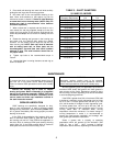
9. Tighten cap bolts to the recommended torque in
Table 2.
10. Assure that there is running clearance at seal ring as
shown on Sketch A.
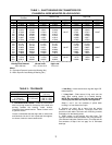
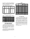
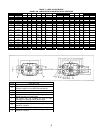
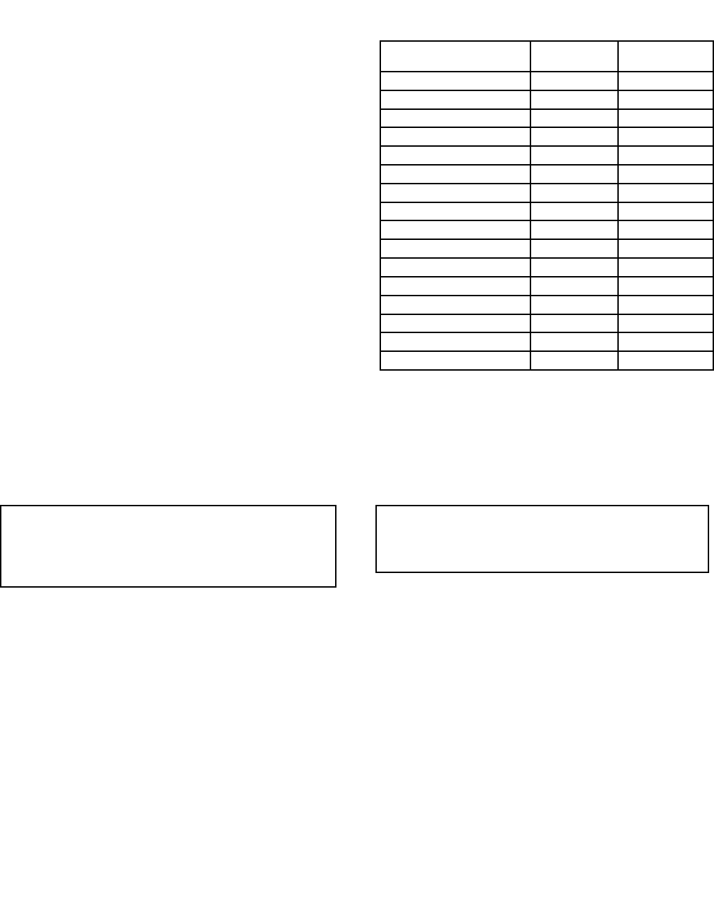
TABLE 3 – SHAFT DIAMETERS
S-2 AND S-3, INCHES
Bearing Bore
Diameter, MM (Inches)
S-2 S-3
75 (2.9528) 3
7
/
16
2
13
/
16
80 (3.1496) 3
5
/
8
3
85 (3.3465) 3
15
/
16
3
3
/
16
90 (3.5493) 4
1
/
8
3
3
/
8
100 (3.9370) 4
1
/
2
3
13
/
16
110 (4.3370) 4
7
/
8
3
3
/
8
120 (4.7244) 5
5
/
16
4
9
/
16
130 (5.1181) 5
7
/
8
4
15
/
16
140 (5.5118) 6
1
/
4
5
5
/
16
150 (5.9055) 6
5
/
8
5
3
/
4
160 (6.2992) 7 6
1
/
16
170 (6.6929) 7
7
/
16
6
7
/
16
180 (7.0866) 7
13
/
16
6
7
/
8
190 (7.4803) 8
3
/
8
7
1
/
4
200 (7.8740) 8
3
/
4
7
5
/
8
220 (8.6614) 9
9
/
16
8
5
/
16
MAINTENANCE
WARNING
To ensure that drive is not unexpectedly started, turn off
and lock out or tag power source before proceeding.
Failure to observe these precautions could result in bodily
injury.
Remove the housing cap in order to inspect
bearing and grease. Before reassembly it is important
that the V-ring seals be removed if TRIPLE TECT seal
installation tools are not available. If available, do not
remove seals and follow cap installation outlined in
the seals instruction manual.
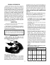
GREASE LUBRICATION
USAF bearings are specifically designed for dirty,
dusty or wet environments. In order to properly protect
bearings during installation, pack the bearing insert 100%
full of grease immediately after having properly mounted
bearing on the shaft.
If the RPM of the application falls between 20% and
80% of maximum RPM (Table 6), pack the lower half of
the housing one half full. If the RPM of the application is
less than 20% of maximum RPM, pack bearing housing
cavity 100% full. If the RPM exceeds 80% of maximum
RPM, pack the lower half of the housing 1/3 full.
WARNING
Regreasing requires rotating parts to be exposed.
Exercise extreme care during such operations. Failure to
observe these precautions could result in bodily injury.
At each regreasing cycle, for applications up to 80% of
maximum RPM, slowly add grease until fresh grease is
seen purging at the seals. Regreasing should be done
while running. Remote regreasing lines should be added
to avoid endangering personnel.
If the RPM is greater than 80% of maximum RPM, add
4 strokes of a handgun at each regreasing cycle for bores
up to 55 mm. For bores greater than 55 mm up to 140
mm, add 8 strokes of handgun at each regreasing cycle.
For bores greater than 140 mm up to 220 mm, add 16
strokes of a handgun at each regreasing cycle. For units
running above 80% of maximum RPM, running
temperature should be monitored. If a drastic change in
running temperature is noted, it is recommended to
remove the used grease completely and recharge with
fresh grease per the above instructions.
Select a grease with a viscosity at operating
temperature which will provide full film lubrication (See
Table 4). Use a 50°F - 100°F increase in bearing
temperature above ambient, depending on RPM and load.
4