


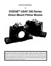

GENERAL INFORMATION
DODGE USAF bearings conform with all appropriate
AFBMA standards. They are available in either adapter or
direct mounting styles for 1
7
/
16
" through 8”, and up to 220
mm diameter shafts. A wide variety of seals is available
including metallic LER, TRIPLE-TECT non-metallic with v-
ring, Drop-in TRIPLE-TECT with neoprene v-ring, Auxiliary
Taconite, or Split non-metallic. TRIPLE-TECT is provided
as standard on complete assemblies. DODGE USAF
housings provide you with maximum application flexibility.
Cast-in dimples allow for easy field modification for vents,
lube ports and sensors. Oversized drains and an oil
equalization hole make USAF ready for circulating oil
systems off the shelf. For hostile environments, USAF
offers optional cast-closed end housings, stainless
hardware kits, and nylon coating. Complete installation,
maintenance, and modification instructions for direct
mounted units are provided in this manual. Modification
instructions are shown on Table 7.
INSPECTION
Inspect shaft. Ensure that the shaft is smooth, straight,
clean, and within commercial tolerances.
Inspect bearing. Do not allow bearing to be exposed to
any dirt or moisture. Do not remove slushing compound as
it acts as both a protectant and lubricant and is also
compatible with standard greases.
WARNING
To ensure that drive is not unexpectedly started, turn off
and lock out or tag power source before proceeding.
Failure to observe these precautions could result in bodily
injury.
INSTALLATION
NOTE: Housing caps and bases are not
interchangeable; they must be matched with mating
half. Install non-expansion bearing first.
DIRECT MOUNTED BEARINGS
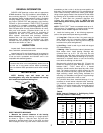
1. Measure the internal clearance of the bearing
before mounting. Place the bearing in a upright position
as shown in Figure 1. Seat the inner ring and roller
elements by pressing down firmly on the inner ring bore
while rotating the inner ring a few times. Position the roller
assemblies so that a roller is at the top-most position on
both sides. For bore sizes above 6½” only, press these top
rollers inward ensuring contact with center guide flange.
Using a feeler gauge measure the clearance for both sides
by inserting as far as possible and sliding over top of roller
(Figure 1). Write down the measured clearance and
compare with specifications (Table A). NOTE: Do not
rotate bearing when moving feeler between roller and
outer ring.
NOTE: TRIPLE TECT
™
seals are standard seals up to 10
(220 mm) bore. For assistance in installing seals use seal
instruction manual 499665 supplied with the seals.
2. Install the bearing parts in the following sequence:
(refer to the replacement parts drawing and table.)
a) V-ring Seal – Slide one of the V-ring seals onto the
shaft, making sure lip is toward the bearing. (NOTE:
Do not install V-ring seal on seal ring until housing cap
has been set in place and tightened.)
b) Seal Ring – Install a seal ring on shaft with largest
O.D. toward bearing.
c) Bearing – Make sure that the internal clearance has
been written down. Install bearing. Bearings with
cylindrical bore up to 2¾ (70 mm) may be cold
mounted on the shaft. Apply coat of light oil to the shaft
and bearing bore, then press the bearing on by using a
mechanical or hydraulic device or use the mounting
nut to drive the bearing onto the shaft.
Bearings with cylindrical bore above 2¾ (70 mm) are
heated for mounting on shaft. Bearings, heated in oil
between 200°F - 215°F, when still in a heated
condition, should have the bore wiped dry with a clean
cloth. The bearing should be rapidly pushed on the
shaft and positioned squarely against the shoulder. A
slight screwing motion during fitting facilitates the
mounting. It is advisable to use gloves. Large bearings
are generally handled with a hoist or crane.
For cylindrical bore direct mounted bearings, it is not
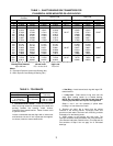
necessary to check internal clearance after mounting.
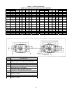
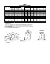
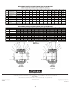
It is, however, important to verify the shaft diameters
(Tables 1 & 2) and to measure the unmounted internal
clearance to ensure conformance to specifications
(Table A).
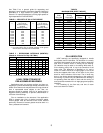
Table A.
Radial Internal Clearance in Self-Aligning Roller
Bearings (Values in .0000 inches)
Bore Diameter
MM
With Cylindrical Bore
Over Incl. Low High
14 24 14 18
24 30 16 22
30 40 18 24
40 50 22 30
50 65 26 36
65 80 32 44
80 100 39 53
120 140 57 75
140 160 65 87
160 180 71 95
180 200 79 103
200 225 87 114
2