


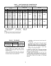
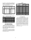

TABLE 1 – SHAFT B
EARING SEAT DIAMETERS FOR
CYLINDRICAL BORE MOUNTED PILLOW BLOCKS
Bearing Bore
Diameter
Normal Load High Load
MM Inches Shaft Diameter (S-1) MEAN Shaft Diameter (S-1) MEAN
Nom. Max. Min. Max. Min. FIT Max. Min. FIT
75 2.9528 2.9522 2.9540 2.9532 .0011T 2.9543 2.9536 .0014T
80 3.1496 3.1490 3.1508 3.1500 3.1511 3.1504 .0015T
85 3.3464 3.3457 3.3179 3.3470 3.3484 3.3475
90 3.5433 3.5425 3.5447 3.5438 3.5452 3.5443
95 3.7402 3.7394 3.7416 3.7407 .0014T 3.7421 3.7412 .0019T
100 3.9370 3.9362 3.9384 3.9375 3.9389 3.9380
105 4.1338 4.1331 4.1353 4.1344 4.1358 4.1349
110 4.3307 4.3299 4.3321 4.3312 4.3326 4.3317
120 4.7244 4.7236 4.7258 4.7249 4.7263 4.7254
125 4.9212 4.9203 4.9229 4.9219 4.9235 4.9225
130 5.1181 5.1171 5.1197 5.1187 5.1203 5.1193
140 5.5118 5.5108 5.5134 5.5124 5.5140 5.5130
150 5.9055 5.9045 5.9071 5.9061 .0016T 5.9077 5.9067 .0022T
160 6.2992 6.2982 6.3008 6.2998 6.3014 6.3004
170 6.6929 6.6919 6.6945 6.6935 6.6951 6.6941
180 7.0866 7.0856 7.0882 7.0872 7.0888 7.0878
190 7.4803 7.4791 7.4821 7.4809 7.4829 7.4817 .0026T
200 7.8740 7.8728 7.8758 7.8746 .0019T 7.8772 7.8760 .0032T
220 8.6614 8.6602 8.6632 8.6620 8.6646 8.6634
These fits apply to roller bearings with inner ring rotation under radial and thrust loads.
Bearing Bore Diameter Normal Load High Load
Up to 220 mm P/C = 0.10 to 0.15 P/C>0.15
Where
P = Equivalent Dynamic Load on the Bearing (lbs.)
C = Basic Dynamic Load Rating of Bearing (lbs.)
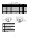
TABLE 2 – TOLERANCE
Shaft Diameter (S-2 & S3)
Over Including Tolerance
2" (50 mm) 4" (100 mm) +.000" to -.004"
4" (100 mm) 6" (150 mm) +.000" to -.005"
Over 6" (150 mm) +.000" to -.006"
d. Lockwasher and Locknut – Install the lock-washer
with inner prong located in the keyway of the shaft and
pointing towards the bearing. Install locknut,
chamfered face toward bearing. Tighten locknut using
a spanner wrench.
Locate a lockwasher tab that aligns with a locknut slot
and bend tab into slot. If slot is past tab, then tighten,
not loosen, locknut to meet a washer tab.
e. Seal Ring – Install second seal ring with large O.D.
toward locknut.
f. V-ring Seal – Slide second V-ring seal onto the
shaft, again making certain lip is toward bearing.
NOTE: Do not install V–ring seal on seal ring until
housing cap has been set in place and tightened.
Steps e. and f. are not necessary if pillow block
housing is a "cast closed end" style.
3. Remove any paint, dirt or burrs from the mating
surfaces of the housing halves. Thoroughly clean seal
grooves on both sides. Set lower half of housing on base
and apply oil to the bearing seats.
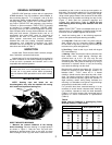
4. Apply grease to the bearing and seal rings. The
lubricant should be smeared between the rolling elements.
(See Grease Lubrication Section below.) This step and the
first sentence of Step 8 do not apply for oil lubricated
bearings.
3