


Deluo Electronics http://www.deluo.com
9
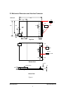
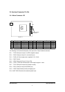
3.4 Interface Connector Pin Out
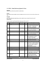
3.4.1 Molex Connector JP3
1
JP3
EverMore
BBP1204
1
10-pin Molex
connector
pin-1
Figure 2
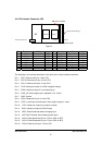
Pin Function Input/Output Level Pin Function Input/Output Level
1 TXD0 Output LVTTL 2 RXD0 Input LVTTL
3 PWR_IN Input 3.3V 4 GND Ground 0V
5 LED0 In/Out LVTTL 6 1PPS Output LVTTL
7 TXD1 Output LVTTL 8 RXD1 Input LVTTL
9 VBAT Input 3.3V 10 ANT PWR Input
The following is a functional description of the pins on the 10-pin interface connector.
Pin 1. TXD0: Serial port output # 1 (GPS navigation output)
Pin 2. RXD0: Serial port input # 1 (command input)
Pin 3. PWR_IN: Power supply input, regulated 3.3V, 112mA
Pin 4. GND: Ground
Pin 5. LED0: Reserved I/O port 31 from CPU
Pin 6. 1PPS: 1-pulse-per-second output. Active high for approx. 1usec
Pin 7. TXD1: Serial port output #2 (currently unused)
Pin 8. RXD1: Serial port input #2 (DGPS input)
Pin 9. VBAT: External backup battery charging input
Pin 10. ANT PWR: External active antenna power input