


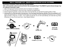

WIRING INSTRUCTIONS
PROGRAM/OVERRIDE SWITCH: 2 PIN PLUG
This switch is used for programming features, transmitters, valet mode, and to override the optional starter disable (if
installed) in the event of a non-operating remote control.
LED: 2 PIN PLUG
The LED is used as a VALET/PROGRAMMING indicator and it will also FLASH for use as security deterrent when the
optional ANTI-GRIND/STARTER DISABLE output is programmed.
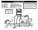
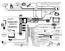
12 PIN PLUG:
PIN 1: WHITE: +12V or (-) NEGATIVE PARKING LIGHT OUTPUT:
Connect to vehicle parking light circuit at the back of light switch or if this is not possible, connect directly to one of the
parking lights at the front of the vehicle. If your vehicle has a multiplex lighting system that requires a (-) Negative parking
light output, then open the access door on the top of the module and move the jumper. SEE JUMPER PLUG DIAGRAM
PAGE 8. Some European vehicles require separate left and right circuits. Use a dual relay or diodes to isolate the output.
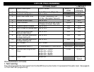
NOTES: (1) Default parking light output is +12 volts. (2) Use an external relay for vehicles that draw excess
current from extra running lights, light bars, or trailers. Parking light output is limited to +15/-.5 AMPS only.
PIN 2: YELLOW/WHITE: (-) HORN CHIRP/HONK OUTPUT
Connect to the Negative Horn Trigger wire usually located near the steering column. If the vehicle horn circuit requires
+12V, then a relay is required. RELAY WIRING: Connect the Yellow/White wire to terminal 85, connect relay terminals 86
and 87 to +12V constant power. Connect terminal 30 of the relay to the +12V positive Horn activation wire.
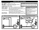
PIN 3: BLACK: MAIN SYSTEM GROUND
Connect to chassis metal of the vehicle. An existing bolt or screw may provide an adequate ground, or drill a small hole,
scrape away paint and attach using a sheet metal screw & star washer. This wire must be connected to a proper ground
or undesirable and inconsistent operation will occur. Do not use Factory ground locations.
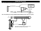
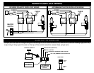
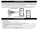
PIN 4: YELLOW/BLACK: (-) IGNITION OUTPUT -or- ANTI-GRIND/STARTER DISABLE OUTPUT
This negative output wire is programmable and can function two different ways. It can be used as a Negative Ignition
output for GM Anti-theft and Transponder Bypass modules, or it can be programmed to function as an Anti grind/Starter
Disable output. As a Negative Ignition wire, this wire activated when the remote start button is pressed and stays on
through the duration of the remote start. As an Anti grind/Starter disable this wire activates when the Lock button on the
remote is pressed and during remote start. When using this wire for an Anti grind/Starter disable, an optional Relay is
needed to interrupt the Starter circuit. The starter disable circuit adds an anti-theft feature to this remote start system and
to prevent accidental grinding of the starter if key is turned to far after a remote start. See diagrams on NEXT PAGE.