


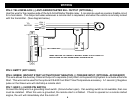
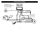
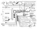

WIRING
PIN 4: YELLOW/BLACK: (-) ANTI-GRIND/STARTER KILL OUTPUT (OPTIONAL)
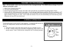
Use this wire for the negative side of the Anti-Grind/Starter Disable relay. It can also be used as a sensor disable circuit
for a host alarm. This output activates whenever a remote start is requested, and when the vehicle is remotely locked
with the transmitter. (See diagram below)
TO
IGN 2
MOTOR
ACC
START
CUT
BROWN
YELLOW/BLACK
8685
MAKE CERTAIN TO CONNECT "BROWN" START OUTPUT WIRE TO
MOTOR SIDE OF ANTI-GRIND/START DISABLE RELAY.
IGN 1
PIN 5: EMPTY (NOT USED)
PIN 6: GREEN: INSTANT START ACTIVATION BY NEGATIVE (-) TRIGGER INPUT (OPTIONAL ACCESSORY)
This wire allows the Auxiliary Channel Output of a separate (host) Alarm or Keyless Entry System to activate a Remote
Start. This wire can be used for the optional CS-400 Cool Start Timer/Temperature accessory. A 1 second (-) Negative
pulse on the Green wire will start/stop a remote start.
PIN 7: GRAY: (-) HOOD PIN SWITCH
Connect the Gray wire to a grounding hood switch. (Ground when open). If an existing switch is not available, then one
must be installed. When this wire is grounded, the remote start is inhibited. If hood is opened on a remote started
engine, the unit will immediately shut the motor off.
4