


WIRING INSTRUCTIONS
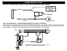
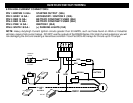
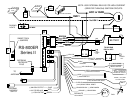
YELLOW / YELLOW/WHITE (-) IGN. & (-) ACC. OUTPUTS (GROUND WHEN RUNNING):
YELLOW
85
86
30 87
2nd IGN
(If needed)
IGN SW.
OR
ANTI-THEFT/
MODULE
+12V CONSTANT
OR
TRANSPONDER
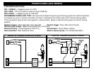
PIN 4: YELLOW/BLACK: (-) ANTI-GRIND/STARTER KILL OUTPUT (OPTIONAL)
Use this wire for the negative side of the Anti-Grind/Starter Disable relay. It can also be used as a sensor disable circuit
for a host alarm. This output activates whenever a remote start is requested, and when the vehicle is remotely locked with
the transmitter. The output can also be programmed to activate passively. (See diagram)
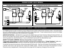
TO
IGN 2
MOTOR
ACC
START
CUT
BROWN
YELLOW/BLACK
8685
MAKE CERTAIN TO CONNECT "BROWN" START OUTPUT WIRE TO
MOTOR SIDE OF ANTI-GRIND/START DISABLE RELAY.
IGN 1