


INSTALLATION CAUTIONS & WARNINGS
**FOR SAFETY REASONS, DO NOT INSTALL THE RS800 Series II in vehicles with MANUAL TRANSMISSIONS.**
If accidentally left in gear, a remote started vehicle could become a self-propelled threat to life and property.
WARNING: This system does NOT have engine over-rev protection. Make certain vehicle throttle linkage operates
properly and does not stick. A stuck throttle will cause severe engine damage
DO NOT extend the RS800 Series II Ignition harness length. Mount the module so that main harness reaches all ignition
switch wiring. Extending these wires could result in poor performance.
DO NOT route any wiring that may become entangled with brake, and gas pedals, steering column, or any other moving
parts in the vehicle.
DO NOT exceed the rated output current of any circuit on the Remote start module. Failure to observe this warning will
result in damage to the unit not covered under warranty.
DO NOT remote start the vehicle in a closed garage. Make sure that the garage door is open or there is adequate
ventilation. Failure to observe this rule could result in injury or death from poisonous Carbon Monoxide fumes.
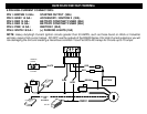
WIRING INSTRUCTIONS
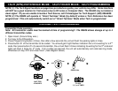
2 PIN PLUG-PROGRAM/OVERRIDE SWITCH:
This switch is used for programming features, transmitters, valet mode, and must be used to override the Starter Disable
(if optional feature installed) in the event of a non-operating remote control.
2 PIN PLUG-(OPTIONAL) LED:
The LED is used as an indicator for Valet, Programming, and for use as security deterrent with the optional ANTI-
GRIND/STARTER DISABLE feature installed. Mount in a visible location on the dash or in the console.
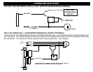
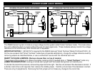
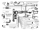
PIN 1 & 2: YELLOW / YELLOW/WHITE: (-) IGN / (-) ACC OUTPUTS (FOR ADDING RELAYS)
Use these wires when the vehicle requires a second IGNITION or ACCESSORY circuit to be activated. This occurs on
Toyota, late GM, and other models of vehicles. This wire is also used to activate ANTI-THEFT or TRANSPONDER
Bypass Modules. Connect to the “ground when running” input of the bypass module. (See Diagram on NEXT PAGE.)
PIN 3: BLACK: MAIN SYSTEM GROUND
Connect to chassis metal of the vehicle. An existing bolt or screw MAY provide an adequate ground, or drill a small hole,
scrape away paint and attach using a sheet metal screw & star washer. This wire MUST be connected to a good ground
or undesirable and inconsistent operation will occur.