


WIRING INSTRUCTIONS
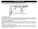
PIN 4: YELLOW/BLACK: (-) ANTI-GRIND/STARTER KILL OUTPUT (OPTIONAL)
Use this wire for the negative side of the Anti-Grind/Starter Disable relay. It can also be used as a sensor disable circuit
for a host alarm. This output activates whenever a remote start is requested.
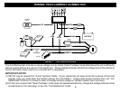
TO
IGN 2
MOTOR
ACC
START
CUT
BROWN
YELLOW/BLACK
8685
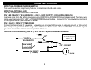
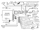
MAKE CERTAIN TO CONNECT "BROWN" START OUTPUT WIRE TO
MOTOR SIDE OF ANTI-GRIND/START DISABLE RELAY.
IGN 1
PIN 5: EMPTY (NOT USED)
PIN 6: GREEN: INSTANT START ACTIVATION BY NEGATIVE (-) TRIGGER INPUT (OPTIONAL ACCESSORY)
This wire allows the Auxiliary Channel Output of a separate (host) Alarm or Keyless Entry System to activate a Remote
Start. A 1-second (-) Negative pulse on the Green wire will start or stop the engine.
PIN 7: GRAY: (-) HOOD PIN SWITCH
Connect the Gray wire to a switch that is at ground when the hood is open. If an existing switch is not available, then one
must be installed. When this wire is grounded, the remote start is inhibited. If hood is opened on a remote started
engine, the unit will immediately shut the motor off. If hood is open before a remote start unit will not attempt to start
engine.
PIN 8: PINK: (+12V) DIESEL GLOW PLUG INPUT
Connect Pink wire to indicator circuit that shows +12 volts while the “WAIT TO START LAMP” is on. When this wire is
used, the system will wait until light turns off before attempting a remote start. Note: For vehicles that have a Negative
Wait to Start lamp an extra relay is required.
4