


WIRING INSTRUCTIONS
2 PIN PLUG-PROGRAM/OVERRIDE SWITCH:
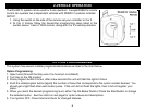
This switch is used for programming features, remote transmitters & valet mode.
2 PIN PLUG-(OPTIONAL) LED:
The LED is used as an indicator for Valet mode.
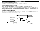
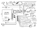
PIN 1 & 2: YELLOW / YELLOW/WHITE: (-) IGN / (-) ACC OUTPUTS (FOR ADDING RELAYS)
Use these wires when the vehicle requires a second IGNITION or ACCESSORY circuit to be activated. The Yellow wire
is also used to activate ANTI-THEFT or TRANSPONDER Bypass Modules. Connect to the “ground when running” input
of the bypass module. (See Diagram on Below.)
PIN 3: BLACK: MAIN SYSTEM GROUND
Connect to chassis metal of the vehicle. An existing bolt or screw MAY provide an adequate ground, or drill a small
hole, scrape away paint and attach using a sheet metal screw & star washer. This wire MUST be connected to a good
ground or undesirable and inconsistent operation will occur.
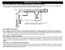
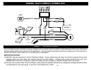
YELLOW / YELLOW/WHITE (-) IGN. & (-) ACC. OUTPUTS (GROUND WHEN RUNNING):
YELLOW or
85
86
30 87
2nd IGN/ACC
(If needed)
IGN SW.
OR
ANTI-THEFT/
MODULE
+12V CONSTANT
OR
TRANSPONDER
Diode isolate
if using both!
YELLOW/WHITE
3