


3
WIRING
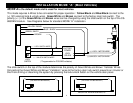
(2) VIOLET WIRES: ON-BOARD RELAY (10A) IMMOBILIZER CIRCUIT #1 NORMALLY OPEN
These wires come directly from the terminals of an on-board Relay to immobilize the Coil or Fuel Pump Circuit in
the vehicle. Selected the circuit you want to interrupt, cut it, and connect each cut end to a VIOLET wire.
NOTE (1): This is a high-security, normally open connection. If the alarm system is unplugged or loses
power, the circuit will still be immobilized!
NOTE (2): This circuit has a maximum load of 10A and should NOT be used to interrupt a high current
wire such as an Ignition supply or Starter circuit from the ignition switch!
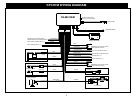
WHITE/RED: (-) NEGATIVE HORN/SIREN OUTPUT
Connect to wire that activates the factory horn. If you choose to use this output with a standard alarm (warble)
siren, then it should be connected to the black (negative) wire of the siren. Connect the red wire of the siren to
constant (+) 12 Volts. NOTE: This wire is preset for a factory vehicle horn. You must change the programming for
siren use. See option #15.
BLACK WIRE: SYSTEM CHASSIS GROUND
THIS WIRE MUST BE CONNECTED TO CHASSIS METAL OF THE VEHICLE. Scrape away any paint or dirt
from the area to ensure a good connection.
RED WIRE: +12V POWER INPUT (15 amp fuse)
Connect to +12 Volt source with supplied fuse & holder. Connect to the vehicle’s battery Positive terminal.
(2) WHITE WIRES: +12V FLASHING PARKING LIGHT OUTPUTS (10 amp fused)
Connect ONE of the white wires to the switched parking light wire at back of light switch, the kick panel or
fusebox. If these locations are not possible, connect directly to one of the parking lights at the front of the vehicle.
NOTE: Many European vehicles require separate right and left circuits. Use this second white wire to
connect to the 2
nd
light circuit on your European vehicle, otherwise do not use both white wires.
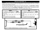
ORANGE WIRE: (-) NEGATIVE STARTER DISABLE (Armed output)
Ground output when system is armed. This output is used for disabling the starter or to activate other optional
devices such as scanner LED’s, window control modules, voice modules etc. For starter kill, cut starter wire and
connect between 87A and 30 on a relay. Connect orange wire to 85 and connect 86 to an Ignition source that
has voltage in “ON” and “CRANKING” positions at the Ignition switch. (Starter disable relay not included)