


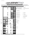
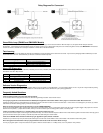
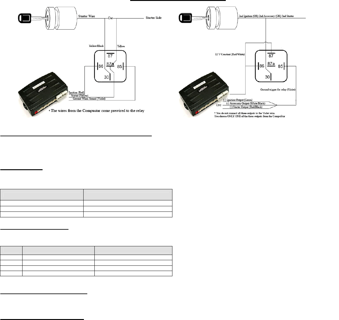
Relay Diagrams For Connector 1
Green/White Loop (CM4000 and CM4200DX Models)
This loop wire determines the transmission setting. The default position (uncut loop) is for manual transmissions. When the loop is cut, the system will be ready for automatic
transmissions. In the default (manual transmission) mode, the system must be set up in Reservation mode prior to the vehicle being able to remote start. IMPORTANT: All warranties
or claims are void if a controller with a cut loop is installed on a vehicle with a manual transmission.
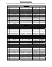
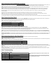
Tach Learning
When you go to learn th
amount then there is an error. This table shows you what the second set of flashes represent.
e tach by holding the foot brake and holding the remote start button for 2.5 seconds on the remote. If you see three parking light flashes followed by a certain
Alarm LED Diagnostics
When the alarm is triggered the LED o
intended for users with 1 Way remotes.
Number of Parking Light Flashes
Tach Error
1 Option 2-10 is not in default setting 1
2 Key is in the off position
3 Bad tach signal. Find a different wire.
n the RPS (if installed), Secure Valet (if installed) and the LED (if installed) will flash a certain amount of times as shown in the table below. This is
Priority Trigger LED Flash Diagnostic
1
Door/Hood Triggered 2 t /Trunk/Ign flashes, rest, then repea
2 2
nd
Shock Triggered 3 flashes, rest, then repeat
3
2
nd
ed Auxiliary Input Trigger 4 flashes, rest, then repeat
4 Panic with remote 5 flashes, rest, then repeat
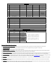
Software Version Diagnostics
This is a new feature added with V.33 or newer software. When you turn the ignition on and hold buttons I + IV on the 2 Way remotes or Lock + Key on the 1 Way remotes the parking
lights and LED will flash to show which version software is on the control module. Version 33 will show up as 2 parking light flashes.
Frequently Asked Questions
I have everything hooked up and the system will not respond.
A: The remotes need to be programmed. Review the “Remote Prog
I am trying to program the control module with the OP500 Option Programmer and it flashes “ER 02” when I plug it in to the antenna cable. What should I do?
A: Make sure that the system is not locked/armed. The last thing to check is the antenna cable or antenna extension cable – make sure this is not damaged. If you need to, try another
cable. When the OP500 is working properly, it will read “success good.”
Where do the blue and purple wires off the extra relay go on the CM4000/CM4200DX?
A: This is a pre-wired positive output, negative trigger relay. Use the secondary ignition, starter, and accessory outputs from CN 3 to give a negative trigger to the purple wire. This will
determine the12V positive (+) output of the blue wire, which you can then connect to your secondary ignition, starter, or accessory wire.
I need
A: You can use the starter output on CN1 that goes to the starter kill relay. You must cut this wire a
ground, it won’t back feed to your accessory. Install the stripe side of the diode facing the control module.
I hav
A: Make sure you have the 4 pin to 6 pin antenna cable and that you have the most current software on the con
Drive Lock (Ignition Controlled Door Locks) are programmed and tach set but still do not function. What is wrong?
A: Once you program Option 1-09 you must also turn the option on with the remote. Buttons I + IV 2 Way remote, Lock + Key
ramming Procedure” section of this manual.
a ground when armed wire for i.e. window modules, does control module have one?
nd place a diode in line so that when the ignition on the other side of the relay goes to
e the Pro 2WSSR remote and antenna and am trying to upgrade the system, what do I need/do?
trol module. This should be Version 28 or greater.
buttons 1 Way remotes.