


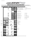

Additional Items to Install
Antenna Usually mounted on the front windshield. Stay at least 1 to 2 inches away from metal and try to mount below the tint stripe.
CompuShock Detects impacts to the vehicle. Can be zip-tied to a wire harness or mounted with the supplied hardware.
RPS Remote Paging Sensor is used to page the remote from the vehicle. Usually mounted in the front windshield. Can also unlock/disarm your system.
Secure Valet Switch Enables the use of Secure Valet mode, mount where the customer will have convenient access.
LED Bright blue flashing LED used as a theft deterrent. Usually mounted to a knockout panel or surface. LED output is 3 volts.
Siren Six tone siren usually mounted in the engine bay.
Thermistor Senses the current temperature in the vehicle. This item is connected to a port on the back side of the controller and does not need programming to turn on.
Remote Programming Procedure
Before you can program the remote(s) you must complete installation. Otherwise the only wires needed to program the remote(s) are the 12v (+) constant wires (red and red/white), the
ground wire (black), and the ignition wire (green). You must have the antenna connected to the main controller. Here are the steps for remote programming:
STEP 1: Turn the key in the ignition from the Off or ACC to the On or IGN position 5 times within 7 seconds. After the 5
th
ignition cycle you will hear the parking light relay click. This will
happen after the 5
th
cycle so it is easy to miss. If you hear two relay clicks and parking light flashes, the system has just exited remote programming mode.
STEP 2: Right after the 5
th
cycle and hearing the first relay click:
A. 1-Way Remote: Tap the lock button on the remote for 0.5 seconds.
B. 2-Way Remote: Tap button I for 0.5 seconds. Pro 2WSSR place battery in remote.
STEP 3: After tapping the button on the remote, you will hear the parking light relay click once to indicate that it has accepted the remote. If you have other remotes to program to the
system, repeat step 2 for each remote, one after the other. Each system can accept three remotes with the exception of the P2WSSR.
Remote Programming with the Secure Valet Switch – Option 3-10 Setting III
If you install the Secure Valet Switch you must program Option 3-10 to setting III. Entering the code is now the only option to coding remotes. The default code is 3, 3. Upon entering
the code you will hear the parking light relay click. Follow the steps in the remote programming procedure above. See the section in this manual regarding Programming the Secure
Valet Switch.
Updating Control Module Software
The Research and Development Team at Firstech is constantly changing software to bring you quality product. If you are unsure which version your control module you have please
check the Dealer Support section of www.compustar.com
for information. We recommend updating the control module before installation. The instructions on how to complete this
procedure are also available at www.compustar.com
. Here is a list of the items needed to update your control module which are also included with the OP500 Option Programmer:
1. CM4000 Control Module
2. Secure Valet Switch
3. USB WebLink Updater
4. Y-cable (shown on www.compustar.com
)
Setting the RPS (Remote Paging Sensor) Code
Basic RPS and car call functions do not require programming. To set the unlock/disarm code you must perform the following procedures:
STEP 1: Disarm/unlock the system (remote must be programmed first)
STEP 2: Turn ignition key to the “on” position and leave the driver’s door open.
STEP 3: Knock on the windshield in front of the RPS a total of 10 times (each time you knock the LED on the RPS will flash RED). The LED will begin to flash rapidly in BLUE with
successful completion of this step.
STEP 4: Enter the first digit of the desired four-digit pass code by knocking on the windshield in front of the RPS the desired number of times. For example, to enter 3, knock on the
sensor 3 times (each time you knock the LED will flash RED) then wait.
STEP 5: The LED on the RPS will confirm your first number by flashing BLUE slowly. Once the LED begins to flash rapidly in BLUE, enter your second number by repeating step 4.
STEP 6: Repeat steps 4 & 5 to enter all four numbers.
STEP 7: Turn the ignition OFF - the RPS disarm/unlock feature is now programmed. Follow steps 3 – 5 to enter your disarm/unlock code.
Programming the Secure Valet Code
The optional Secure Valet Switch prevents the alarm from being put into valet mode through cycling the ignition on/off five times. The Secure Valet Switch is more secure than traditional
toggle / valet switches because it requires a two-digit code. (Default code is 3, 3) IMPORTANT: The first two-digits of the RPS unlock/disarm pass code will be the default pass code for
the secure valet – you do not need to program them independently. If you are not using the RPS unlock, following the below procedures to program your secure valet pass code:
STEP 1: Turn on Option 3-10-III. (Dealer programmed option)
STEP 2: Disarm/unlock the system and turn ignition key to the “on” position and leave the driver’s door open.
STEP 3: Hold down the valet switch for 1.5 seconds. The LED on the valet switch will begin to flash rapidly in BLUE with successful completion of this step.
STEP 4: Enter the first digit of the desired two-digit pass code by depressing the switch the number of times that coordinates with the desired first number. For example, to enter 3,
depress the switch 3 times, then wait.
STEP 5: The LED will confirm the first number by flashing BLUE slowly. Once the LED begins to flash rapidly, enter your second number by repeating step 4.
STEP 6: Turn the ignition off - the Secure Valet Switch is now programmed. Follow steps 3 – 5 to enter your Secure Valet code.
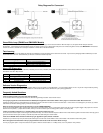
Setting Auxiliary Outputs on Connector 3 – You Must Have the OP500 Option Programmer
To set auxiliary outputs on the CompuStar Pro control modules involves the new Programmable Output Connector wires (POCs). You must choose two odd pin wires on the black 18 pin
connector that you are not using. For example choose POC 8 and 9.
STEP 1: Plug in OP500 and use the Right or Left Arrow Button to scroll through the menu to POC 8 and POC 9 on LCD Line 1.
STEP 2: Use the Up or Down Arrow Button to change the lower number on LCD Line 2 to 10 – Auxiliary 1 or 11- Auxiliary 2.
STEP 3: Scroll up the menu to Option 4-01 and 4-02 and set the options. Please see the Option Table for details.
STEP 4: The Pro control modules have a secure auxiliary option 4-05. This requires you to tap button 4 before you tap button 2 for Aux 1 or button 3 for Aux 2. On 1-Way remotes you
must hold the Trunk and Key/Start buttons for 2.5 seconds then tap the Trunk button for Aux 1 or the Key/Start button for Aux 2.
STEP 5: If you need to change the time settings of the outputs go to AU1 or AU2 on the OP500. LCD Line 2 is the timed output.
STEP 6: Hold the “W” Write button for 3 seconds to set all the options.
Option Settings You Need OP500 For:
Option 2-03 Diesel Timer is default to 10 seconds. To change the time you need the OP500. LCD Line 1 will read DISL after Menu 4.
Option 3-11/3-12 Auxiliary Settings. To change settings with the auxiliary settings you must first set POC9 to 10 and connect to the White wire on the auxiliary settings. The
Auxiliaries 1 through 7 can only be set with the OP500
POC 1 through 9 can only be set with the OP500. They can be changed from default – 0 to anything. Please see the Option Table for details.