


128-6832
5 of 16
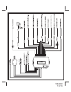
Black/White: Illuminated Entry Output 200 mA (-)
This wire provides a 30 second ground output whenever the system is disarmed using the OEM
transmitter, and pulses ground when the alarm is triggered. It is used to providethe optional entry lighting
feature, and will flash the vehicle's interior light when the system is triggered. This is a transistorized, low
current output, and should only be used to drive an external relay.
3 Pin White Connector: White/Blue, Light Green & Brown. OEM Keyless Entry Inputs
These wires will allow the Factory (OEM) transmitter to arm the system when the LOCK button is pressed,
and disarm the system when the UNLOCK button is pressed.
White/Blue: Arm Input
Connect the white/blue to the lock motor wire of the drives door actuator. The lock motor wire will pulse +12
volts when the LOCK button is pressed on the Factory (OEM) transmitter.
Brown: Disarm Input
Connect the Brown to the unlock motor wire of the drivers door actuator. The unlock motor wire will pulse
+12 volts when the UNLOCK button is pressed on the OEM transmitter. For vehicles with two stage
unlocking, the unlock motor wire of the drivers door actuator will pulse +12 volts when the UNLOCK button
is pressed the first time (unlocking the drivers door), and will not show any pulses the second time the
UNLOCK button is pressed (unlocking all remaining doors) on the OEM transmitter.
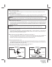
Light Green: Unlock Sense Input
Connect the light green wire to the positive or negative unlock wire from the door lock/unlock switch, or any
passenger door unlock motor wire.
a). For vehicles with two stage unlocking, it is very important that the brown wire does not receive a pulse
when the drivers door only is unlocked using the OEM transmitter.
b). For vehicles with single stage unlocking (all doors unlock with one press of UNLOCK on the OEM
transmitter), connect the brown to chassis ground.
Note: You can select the polartiy of this input by changing DIP Switch #2
2 Pin White Connector: Dash Mounted LED
Route the red and blue wires in the 2 pin white connector from the LED to the control module, and plug it
into the mating white connector on the side of the module.
2 Pin Red Connector: Valet/Override Switch
Route the 2 pin red connector from the override switch previously mounted to the mating two pin
connector on the module.
4 Pin White Connector: IRS-Shock Sensor Harness
Route the 4 pin connector form the previously installed shock sensor to the mating 4 pin connector of the
module.