


128-6832
4 of 16
4
Grey: (-) Hood/Trunk Trigger
This is an instant on ground trigger wire. It must be connected to the previously installed hood and/or
trunk pin switches.
Green: Negative Door Trigger Input
If the vehicle’s courtesy light switches have a (-) ground output when the door is opened (GM and most
Imports), you must connect the Green wire to the negative output from one of the door switches.
WARNING:
Do not use the green wire if the vehicle has + 12 volt output type door switches.(see Purple Wire).
Violet: Positive Door Trigger Input
If the vehicle’s door courtesy light switches have a + 12 volt output when the door is opened (most Fords
and some Imports), you must connect the Violet wire to the positive output from one of the door switches.
In most cases, the Violet wire will only needs to be connected to one door switch, no matter how many
doors the vehicle has.
WARNING:
Do not use the Violet wire if the vehicle has ground output type door switches. (see Green Wire)
Pink: (+) 12 VDC Ignition Source
Connect this wire to the ignition 1 wire from the ignition switch. This wire will show +12 volts when the
ignition key is turned to the to the ON, RUN and START positions, and will have 0 volts when the key is
turned to the OFF and ACCESSORY positions.
Blue: 30 Second Output When ARMED (-) or Passive Door Lock Output (-)
This wire is programmable to provide either a 30second pulsed output when the CA310 is ARMED or a
pulsed ground output to the factory door lock control relay for a passive door locking feature. The
maximum current draw through these outputs must not exceed 300 mA.
3 Wire Ground Switched Door Locks
In this application, the blue wire provides a ground pulse during passive arming, or the pulsed ground
lock output. Connect this wire to the wire that provides a low current ground signal from the factory door
lock switch to the factory door lock control relay.
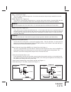
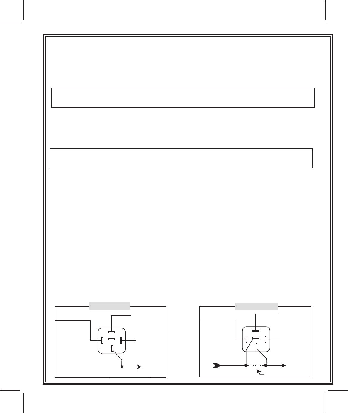
3 Wire Positive Switched Door Locks (Relay required see Diagram 1)
5 Wire Alternating 12 Volt (Relay required see Diagram 2)
X
86
87
85
30
87a
Diagram 2
CUT HERE
+ 12 Volts
Door Lock Switch Door Lock Motor
Lock
Fused + 12v
X
86
87
85
30
87a
CUT HERE
+ 12 Volts
Lock
Diagram1
Fused + 12v
Lock Relay In Vehilce