


128-6832
2 of 16
2
INSTALLATION OF THE MAJOR COMPONENTS
Control Module:
Select a mounting location inside the passenger compartment (behind the dash), and secure using the
two screws provided. The control module can also be secured in place using cable ties. Be certain that the
chosen location will not interfere with the proper operation of the vehicle. Avoid mounting the module to or
routing the wiring around the steering shaft/column, as the module or wiring may wrap around or block the
steering wheel preventing proper control of the vehicle. Secure the module in the chosen location using
cable ties or screws as necessary. Do not mount the module in the engine compartment, as it is not
waterproof.
Siren:
Select a location in the engine compartment that is not accessible from below the vehicle. The selected
location must be clear of hot or moving parts within the engine compartment The siren must be pointed
downward to prevent water retention and the flared end must be pointed away from and out of the engine
compartment for maximum sound distribution. Before securing the siren, check behind your chosen
location to assure that the mounting screws will not penetrate any factory wiring or fluid lines. Secure the
siren mounting bracket using #8 self taping screws or by first using the mounting bracket as a template,
scribe or mark the mounting holes. Drill the marked holes using a 1/8" drill bit, then mount the siren using
#8 sheet metal screws.
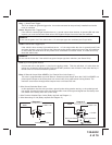
Dash Mounted LED:
A small Red LED included in the kit will serve as a visual indicator of the alarm's status. It should be
installed in the dash, located where it can be easily seen from outside the vehicle, yet not be distracting to
the driver. Once a location has been selected, check behind the panel for wire routing access, and to
confirm the drill will not damage any existing components as it passes through the panel.Drill a 1/4 " hole,
and pass the red and blue wires from the LED through the hole, from the front of the panel. Firmly press the
body of LED into the hole until fully seated.
Valet/Programming/Override Switch
Select a mounting location that is within reach of the ignition switch, as this switch in combination with the
ignition switch, will be used to program the certain features of the system. It is suggested that the switch be
mounted to the lower dash panel in the driver's area within reach of the driver.
Two Stage IR-s Shock Sensor:
Select a solid mounting surface for the shock sensor inside the passenger compartment (behind the dash),
and mount the sensor using cable ties, making sure to allow access to the sensitivity adjustment
potentiometer for use later in the installation.