


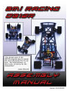
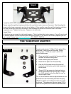
Step 15
Locate the two alloy rear pod plates, the alloy rear
pod plate spacer tube 2 4-40 x 3/8” flat head screws
and 4 4-40 x ¼” flat head screws.
Attach the alloy pod plates to the lower carbon pod
plate with the 4 4-40 x ¼” screws.
Attach the alloy rear pod plate spacer tube to the
allow rear pods with the 2 4-40 x 3/8” screws.
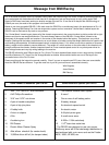
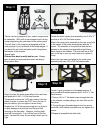
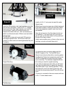
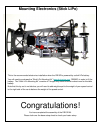
Step 16
Locate and install the two long gray anodized
threaded spacers as shown with 4-40 x ¼” flat
head screws
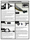
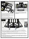
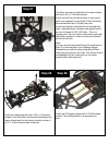
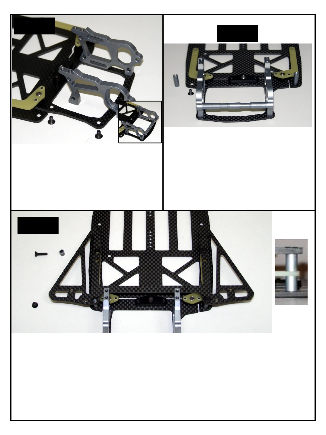
Locate 2 4-40 x ¼” flat head screws, 2 4-40 x ½” flat head screws and 2 gray alloy unthreaded spacers.
1. Attach the carbon chassis brace to the chassis with 2 4-40 x ¼” flat head screws by threading them into
the long gray alloy threaded posts at the rear corners of the chassis.
2. Pass a 4-40 x ½” flat head screw through the countersunk hole at the front of a chassis brace wing.
Slide an alloy gray unthreaded spacer under the carbon chassis brace and pass the 4-40 x ½” flat head
screw through it.
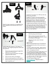
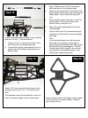
3. Move the flex plate under the 4-40 x ½” flat head screw so the screw passes through the front hole in the
flex plate and finally into the gray alloy threaded spacer you put in the chassis in Step 14. Check out the
small detail photo to check you assembly.
Step 17