


28 © 2001 Directed Electronics, Inc. Vista, CA
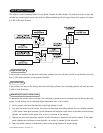
The system is most commonly found in Ford, Mazda, Chrysler and GM vehicles. The door lock switch or door key
cylinder may contain either one or two resistors.
If one resistor is used in the door lock switch/key cylinder, the wire will pulse ground in one direction and resis-
tance to ground when operated in the opposite direction.
If two resistors are used in the factory door lock switch/key cylinder, the door lock switch/key cylinder will read
resistance to ground in both directions.
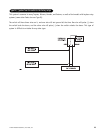
To determine the resistor values, the door lock switch/key cylinder must be isolated from the factory door lock
system. For all testing, use a calibrated digital multimeter that is set to ohms.
1. Cut the output wire from the door lock switch/key cylinder in half.
2. Test with the meter from the switch side of the cut door lock switch/key cylinder wire to a reliable ground
source. Some good ground references are the ground input source to the door lock switch/key cylinder or the
battery ground.
3. Operate the door lock switch/key cylinder in both directions to determine the resistor values. If the multi-
meter displays zero resistance in one direction, no resistor is needed for that direction.
4. Once the resistor value(s) is determined, refer to the wiring diagram for proper wiring.
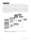
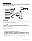
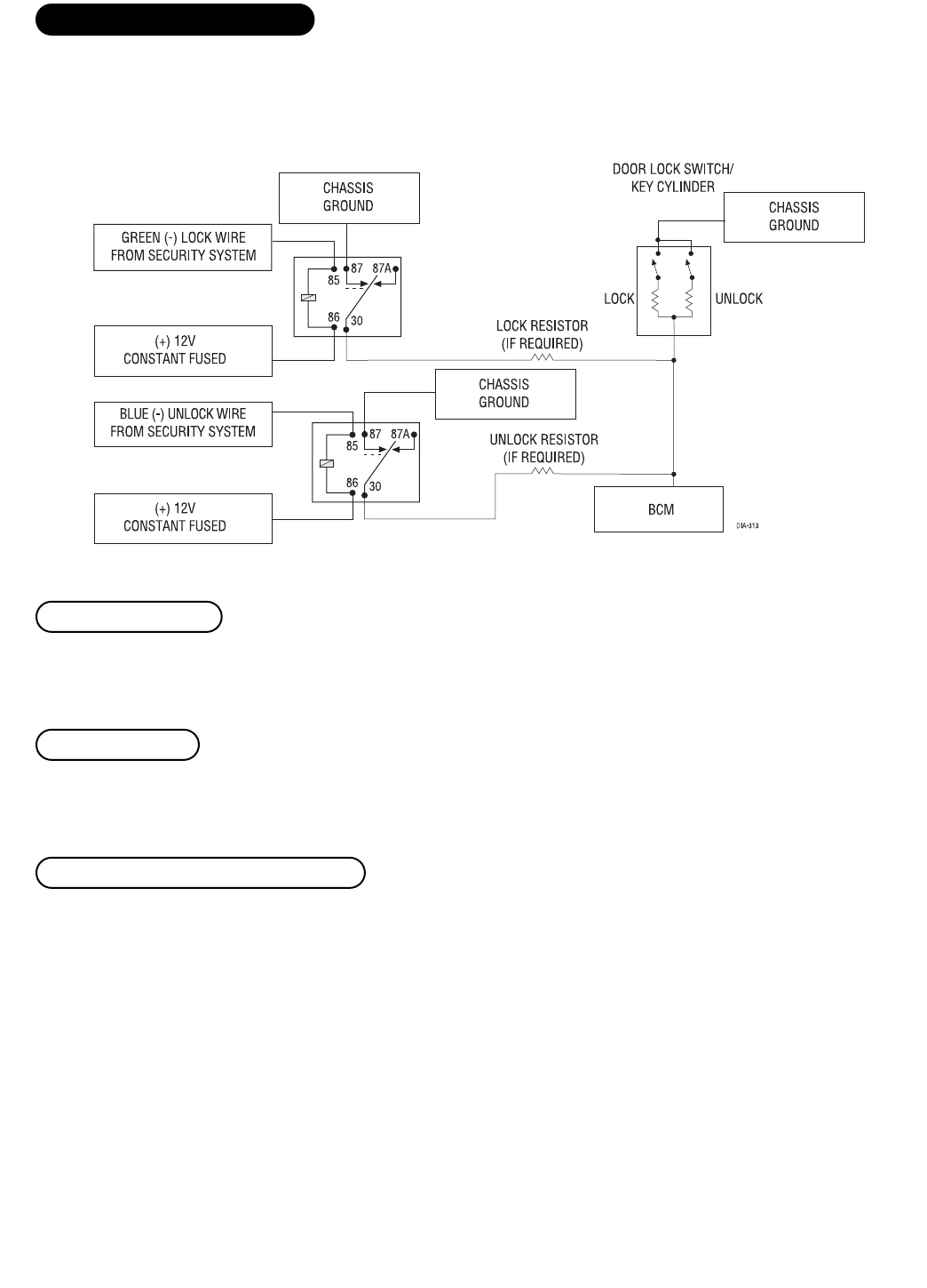
determining the proper resistor values
two-resistor type
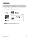
single-resistor type
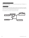
type H: negative (-) multiplex