


14 © 2001 Directed Electronics, Inc. Vista, CA
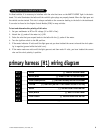
This wire provides a negative output to unlock the vehicle's doors. To interface this output with the vehicle's
power door lock system, see the Door Lock Wiring Guide section of this guide.
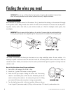
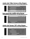
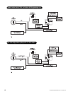
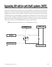
relay satellite key switch interface wire
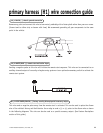
connection guide
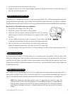
The heavy gauge wires leading from the relay satellite are used to energize high current circuits in the vehicle.
It is crucial that these connections are made correctly so that they are capable of handling the current demands.
For this reason, scotch locks, T-taps and other such connectors should not be used.
Remove the two 30 amp fuses prior to connecting these wires and do not replace them until the satellite has
been plugged into the control module. These wires are the source of current for all the circuits the relay satel-
lite will energize. They must be connected to a high current source. Since the factory supplies (+) 12V to the key
switch that is used to operate the motor, it is recommended that these wires be connected there.
NOTE: If the factory supplies two separate (+) 12V feeds to the ignition switch, connect one RED
wire of the satellite to each feed at the switch.
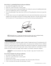
Connect this wire to the ignition wire in the vehicle. (See Finding the Wires You Need section of this guide.)
Connect this wire to the accessory wire in the vehicle that powers the climate control system. (See Finding the
Wires You Need section of this guide.)
Connect this wire to the starter wire in the vehicle. (See Finding the Wires You Need section of this guide.)
Connect this wire to the second ignition wire in the vehicle. (See Finding the Wires You Need section of this guide.)
NOTE: For vehicles that do not have a second ignition wire, this connection is not required.
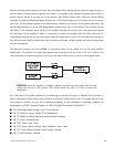
PINK/WHITE (+) output to second ignition circuit
PURPLE (+) starter output
ORANGE (+) accessory output
PINK (+) ignition output
RED (2) (+)12V input for relays
H1/8 LIGHT BLUE (-) door unlock output